
Home › Forums › Environmental Sensors › RS485/Modbus RTU Transducers
- This topic has 3 replies, 1 voice, and was last updated 2016-12-07 at 3:31 PM by
 neilh20.
-
AuthorPosts
-
-
2016-11-30 at 3:21 PM #1826
Discussion on transducers that use “Modbus RTU” serial interfaces, typically half-duplex multi-slave RS485, but sometimes also full duplex point-to-point RS232 .
RS485, as physical link – is ideal for communicating to sensors that are 5~1000m away, with grounds that may be 8V apart.
Less than 15’/5m it would be nice to use USB – but that is a future discussion.
“Modbus RTU” is a mature concept that is very challenged – and is typically implemented on RS485
http://www.modbus.org/docs/Modbus_over_serial_line_V1.pdf
https://en.wikipedia.org/wiki/Modbus
The benefit to consider wired Modbus RTU like communications is it specifies
1) physical RS422/RS485 that is widely available in silicon.
2) the structure of the message, with messaging concepts
3) supplying power 5-24V.
For a new transducer design, with wires SDI-12 might be a lower cost fit. If the transducer can be self powered, or can’t have wires, then a wireless design could be an option.
What “Modbus RTU” doesn’t do, is provide a stamp of conformity. The newer USB, for instance, is a commercial standard, and has a membership organization to specify inter-working and compatibility. USB certification and logo usage are commercial processes, and cost to be part of.
Please share experiences, successes and failures, on using specific transducers. -
2016-11-30 at 4:20 PM #1827
Well my first post on this is to talk about the powering – not as sexy as the protocol, but a base requirement.
Since this is wired, each transducer is going to require power.
Getting powering right is ALWAYS a challenge for a circuit, especially solar powered, low power useage circuits. Its vital to understand the impedance of the power issues.
Wall power supplies are constant impedance and relatively low impedance sources – they can supply say 1 to 2Amps no problem.
Solar panels are variable impedance and relatively high impedance power sources – when its dark there is no power, when the sun is shining it has some power. Batteries and capacitors manage the impedance profile change between a solar panel and the dynamic power used.
In an experiment with a low cost Utopia ULB-I depth gauge – which requires 8-36VDC I recently hit some of the power issues.
It is an example of transducer, and the specification is missing one critical parameter, power used, and inrush current when power is applied.
For a standard wall connected power supply this isn’t a problem.
However I want to take samples every 15minutes and I want it to be off most of the time – so I need an electronic switch in there.
I started by experimenting with a simple boost circuit, and its tripped me up.
The core experiment was taking a “SUNKEE LM2577 DC-DC” I found on amazon – a 5V to 12V boost max@2.5A board (inputrange 4-34,output4-35V), and tying the input to USB +5V switch circuit on the Olimex-H407 board, and the output to the transducer power supply. The Olimex-H407 5V switcher device MP1482DS seemed to be pretty hefty at somewhere around 2A.
I soldered wires to the SUNKEE LM2577 to the H407 USB +5V, and soldered wires to an RJ11 male, and RJ11 female lead to the transducers power/data.
I put a volt meter on the output of the SUNKEE LM2577 adjusted the output to +12V, and left the meter monitoring its voltaage
The power supply supplying H407 was slightly above the minimium of +7V, initially taking about 40mAThen plugged the transducers RJ11s together.
It failed to work!.
As I poked around with a scope I was seeing some of the issues with power supply impedance.
On plugging in the +12V dropped to +7V, and then USB +5V dropped to +3V.I repeated, and monitored the wall supply which kept constant voltage but jumped from 40mA to about 160mA, however it fleeting showed +250mA.
Looking at the switching waveforms on the MP1482DS it wasn’t coping for some reason, so the output was dropping to +3V, which was probably causing the output SUNKEE to droop to +7V – but taking a lot of current in the process.It seems like the MP1482/inductor should have been able to supply at least 1A, but it wasn’t.
I modified the powering, connecting the SUNKEE directly to +5V wall supply, with a current meter.
Hey presto it worked. Watching the +5V wall powersupply, it showed +650mA pulse on plugging in.
While I don’t believe the powersupply’s has a reliable max pulse indication, I did guess that the +5V circuit source is a lower impedance- and so as this was a quick and dirty experiment. It took me less time to do it, than write it up here.
So back to the drawing board.
Generally, in the past for this type of boost powering, what I do is turn on the boost, allow it to power up and fill its output capacitor sufficiently, and then have an electronic switch that switches the steady boosted power directly into the transducer.
If I have an inrush current problem – generally a seat of the pants estimation – I can boost the output capacitor until I solve the problem.
So in this case, I’ve gone back to amazon to order “SunFounder 2 Channel DC 5V Relay Module” – something that I hope I can make work with 3.3V H407 outputs, and switch the +12Vs.For circuit designs I can use lower cost boosters and +12V MOSFET switcher.
-
2016-12-07 at 3:06 PM #1845
I received my dual relay board,
* AtomicMarket.com: 5V Two 2 Channel Relay Module With optocoupler
* SunFounder: 2 Channel DC 5V Relay Module with Optocoupler Low Level Trigger Expansion Board
and the code to drive the relays is pretty simple and is here:
https://bitbucket.org/neilh20/anuttx/commits/daf3e4199ec66c158a3ef20e0da64ec0bcb9f7dbThe purpose is to be able to switch +12V to a Nanolevel capacitance depth gauge and read it over RS485. I’ve been running some tests with the Nanolevel querying it over RS485, and the results have been pretty stable as temperature has varied. However in the solar powered, minimal power useage, the Nanolevel needs to be off most of the time, power switched to it when its going to be used, a pause to allow it to stabilize, and then read it over RS485.
-
2016-12-07 at 3:31 PM #1846
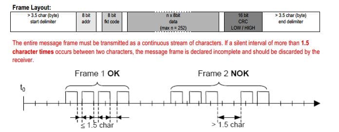
So to query any piece of equipment over a protocol, there are two parts – the physical layer and the data link layer protocol.
https://en.wikipedia.org/wiki/OSI_model
For the nanolevel it specifies physical layer as RS485 (for other equipment it may be the customer SDI-12)
For Keller products the modbus binary “data link layer” there is a document “Keller comm_protocol_series 30 V3.4 2015Oct.pdf”
http://www.kelleramerica.com/manuals-and-software/manuals/series30%20comm_protocol_e.pdf
Every manufacturer that is claiming an open interface, or expects their equipment to network, should supply a description of their implementation of a protocol.
The modbus protocol concept is fairly simple one. IMHO the modbus language is fairly archaic and easier to think of it as a query /response protocol than to try and use the older language associated with register read/writes.
The manufacturers manual is the starting point for understanding what is needed to get data from the device, and there is no such thing as a standardization process for modbusm
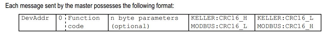
<DevAddr> <FunctionCode> <n byte payload …> <KellerCrc16_H> <KellerCrc16_L>
For Keller a significant difference is that they switch the CRC-16 bytes around from standard modbus !!!
I process this with two functions
rs485crc16add(..) rs485crc16chk(..)
were CRC16calc() does all the magic work with a standard CRCTable
See
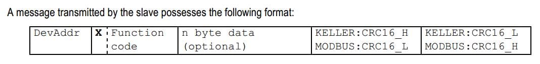
https://bitbucket.org/neilh20/nuttapps/src/5315c5ee8f8fcdb7d5dd69989b499194fc30a034/examples/ae/aelog/ae_mdm_phy.c?at=work_ensy1b&fileviewer=file-view-defaultNow the controlling requestor “master” tx
and the device “slave” responds (looks pretty similar – but the payload is the significant part.
For the first time testing of the protocol, the objective is just to ensure the mechanics are good.
Out 01 03 00 04 00 01 C5 CB – Read Address 4, 1 registers – which is read level
Resp 1 3 2 0 0 B8 44 – Std Crc – result is 0
(or use some of the examples in the manual, though its a bit confusing they don’t all apply to every instrument)Another example – read register 6 (temperature), 2words and interpret the two words as floating point IEEE754
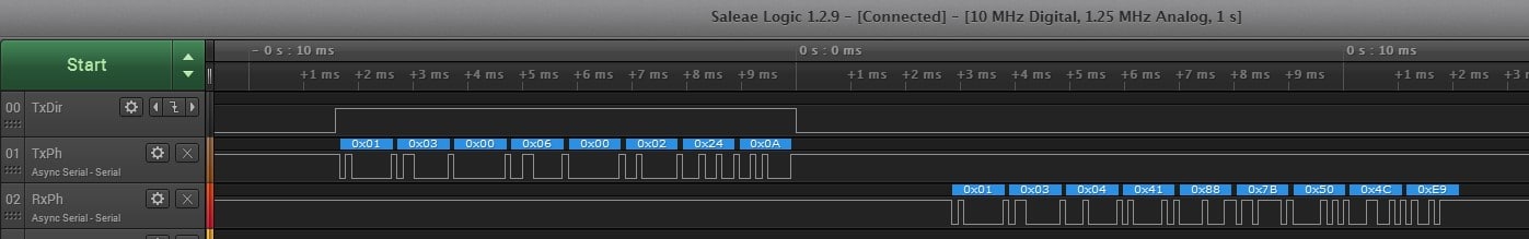
Send 01 03 00 06 00 02 24 0A
Rx 01 03 04 41 88 7B 50 4C E9
Payload: 41 88 C9 48
h-schmidt.net/FloatConverter/IEEE754.html says 17.0 (and the units are C)A Saelig Logic Analyzer trace of this is
-
-
AuthorPosts
- You must be logged in to reply to this topic.