
Home › Forums › Mayfly Data Logger › [rtc] time kept without power (has cr1220)?
- This topic has 12 replies, 3 voices, and was last updated 2016-07-01 at 1:15 PM by
 Shannon Hicks.
-
AuthorPosts
-
-
2016-06-23 at 2:44 PM #1587
Hi relatively new to arduino’s (mostly edit other’s codes). So i have the Mayfly board (CR1220 positive terminal facing up) and am using example from Sodaq RTC library to set the time and then commenting out line 19.
Sodaq example code with line #’s: https://github.com/SodaqMoja/Sodaq_DS3231/blob/master/examples/adjust/adjust.pde
After:
1. uploading code that sets current dateTime (not commenting line 19) ,
2. uploading code that just reads out dateTime (commented line 19 code),
3. unplugging from USB power + communication,
4. letting it sit a few minutes,
5. and plugging the USB power back,the time is reset to 2000-1-1 00:00:00. Is this the normal function? I’d like to unplug power/turn off board with the current time kept.
The only other hardware attached is the microSD card. I’m probably doing something wrong, but I just wanted to make sure. Thanks for any help! -h
-
2016-06-23 at 5:48 PM #1588
We were just about to post the same question. Any insight would be excellent.
Thanks
Dave -
2016-06-23 at 7:13 PM #1589
I haven’t had any problems with the Mayfly boards not retaining the time. I just tested 2 boards that have been on my bench for several months without any external batteries (other than the CR1220) and they both still knew the correct date and time. I then got out 5 new boards, inserted new CR1220 batteries, and then programmed them with the sketch you linked to, first uploading the code with the correct date and time in line 11, then commenting out line 19 and reprogramming it so the board only prints the current date/time on powerup. Leaving the boards for anywhere from 5 to 15 minutes without any external power, then connecting the USB cable, opening the serial terminal, and they all retained the correct time.
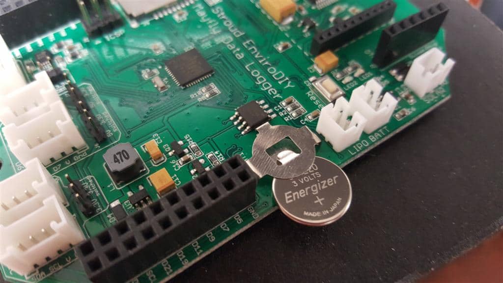
I’ve attached a photo showing the proper orientation for how to insert the battery. Double-check that you inserted it correctly. You should also check the voltage of the battery to make sure it is at 3v. The easiest way to do that is to put one voltmeter lead on the top of the CR1220 battery holder (the positive side), and use the metal housing of the main microSD card socket for the ground. You should see around 3v. If not, then remove the battery and check it outside of the Mayfly. Let me know what you find out.
Attachments:
-
2016-06-23 at 7:30 PM #1591
Thanks for the timely replies!
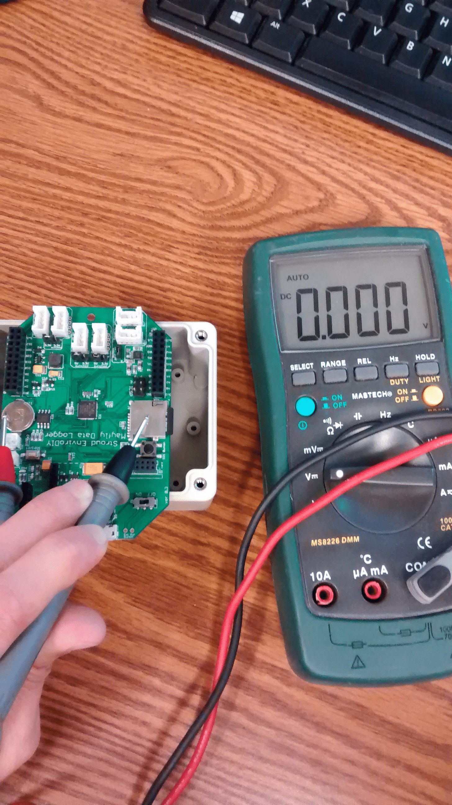
Mine read out zero with positive on the battery housing and ground on the microSD. Pic hopefully attached. (Board in off state and not plugged via USB). Note, i did also change a jumper on one of the Grove connectors to 5V, no sensor/cables attached.
The battery itself is 3V outside of housing. -h
Attachments:
-
2016-06-23 at 8:13 PM #1593
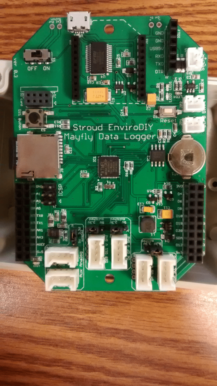
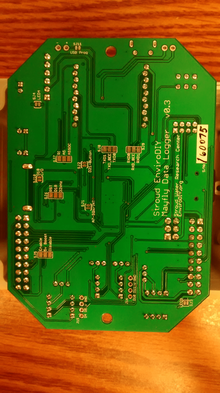
Can you take a focused picture of just the back of the board and one of the front?
-
2016-06-23 at 8:32 PM #1594
Attached. Thanks again for taking your time. Sorry for the time sink. -h
Attachments:
-
2016-06-23 at 10:12 PM #1597
That’s odd that you measure 3v on the battery alone but nothing when it’s installed in the holder on the board. Even a mostly-dead battery should read something besides 0.000v. You usually only see that if there’s a short circuit somewhere on the board (which it doesn’t look like there is, from looking at the photos), but the battery would have been drained pretty quickly, and getting quite hot in the process, and definitely wouldn’t measure at 3v separately.
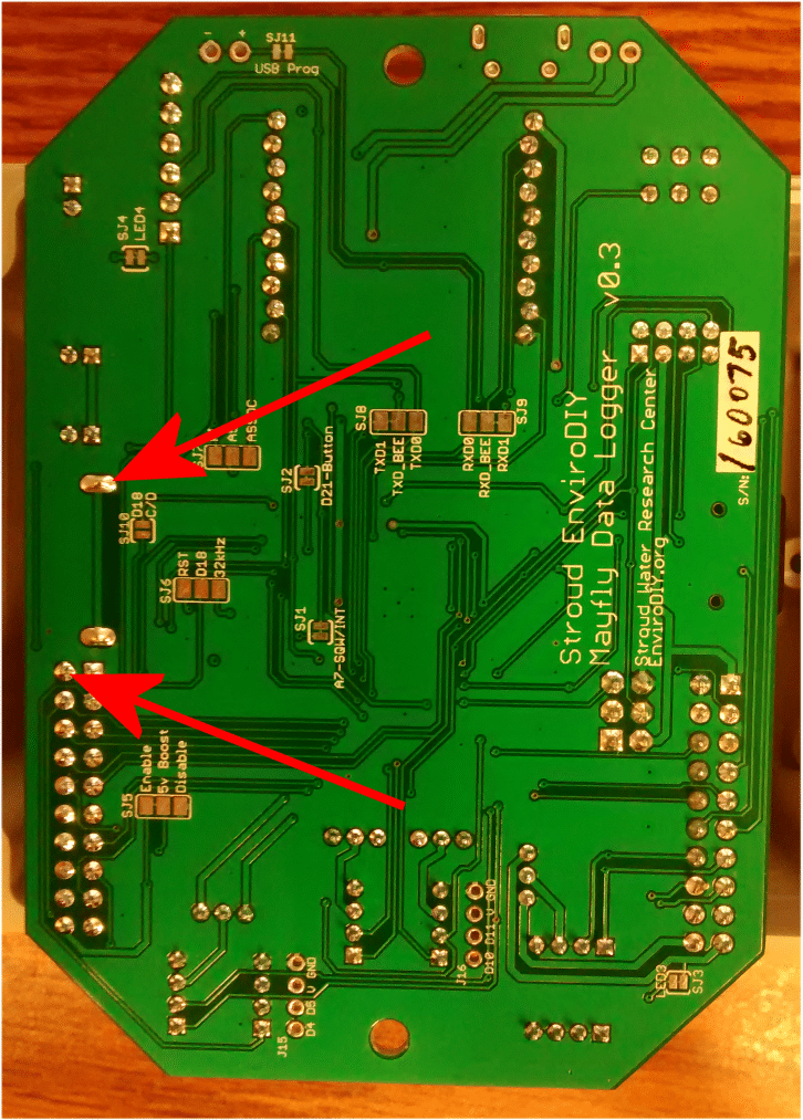
With the battery installed, measure the voltage at the two points shown by the red arrows in the attached picture. That’s the closest 2 points to the battery, so you should see something. If you’re not getting anything, make sure there’s not some tape or plastic anywhere on the battery or inside the holder on the Mayfly. Another thing to check is the shape of the battery. Is it perfectly flat on the negative (bottom) side, and if you set it down on a flat, level surface, can you tell that the battery is resting on only the negative terminal and the edges of the positive outer casing aren’t contacting the surface? What brand of battery is it? Some batteries can become misshapen or were manufactured wrong so they don’t make good contact with board in holders like these. Do you have an extra battery that you can try, or do you have more than one Mayfly board?
Attachments:
-
2016-06-24 at 11:38 AM #1601
Yep, it read 0V on the backside pins. Only 1 Mayfly to test with, (another on its way). I’ll look into batteries. I just passed by the Batteries Plus store for the CR1220.
I believe it’s Nuon brand, but has a “textured” backside: https://www.batteriesplus.com/battery/lithium/1220?q=cr1220
I’ll swing by the BestBuy or look for the Energizer brand on Amazon. Thanks again! -h
-
2016-06-24 at 12:26 PM #1606
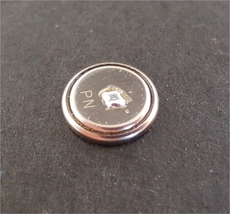
I just did some more testing with a dozen boards. Out of all of them, I found one that exhibited behavior similar to yours. It looks like the green solder mask paint is thick enough on some boards that it is preventing the battery’s negative side from sitting completely flush against the circular ground pad on the Mayfly board. You can easily remedy this by adding a very small layer of solder to the circular pad, if you have a fine enough point on your soldering iron to reach the pad without creating a solder bridge to the metal of the battery connector above it. Or you can solder a very small drop of solder in the center of the battery, like in the attached photo.
Attachments:
-
2016-06-28 at 11:50 AM #1612
Thanks. A colleague, who’s more pro at soldering, got a bit on the pad. RTC kept the time in an overnight off state.
I tried to apply some solder on the negative battery terminal, but couldn’t get and to stick (probably due to some plating).
Anyways, onto figuring out sleep modes and xbee data pushing hehe. Thanks again! -h
-
2016-06-28 at 12:31 PM #1613
I’m glad it worked. We’re working on switching out all of the Amazon inventory with new boards and we’ll be testing each of them first for proper battery connections. It can sometimes be hard to solder to a battery which is why I suggested doing the board first. The next run of boards will have a different battery holder and board footprint so this issue can be avoided.
I’ve got some sketches about sleeping the Mayfly, I’ll try to post them soon. I’ve got a backlog of software examples to post, but also dealing with hardware and inventory stuff, so we’re rather busy here. It’s helpful to get requests from people so I know where to concentrate my efforts. Thanks for the heads up about the battery issue.
DaveE, did you have a similar problem with your board?
-
2016-06-28 at 2:10 PM #1616
Yes, we have two boards and both showed the same behavior. We got one working yesterday — still fooling around with the other one.
Thanks for the helpful posts!
Dave
-
-
2016-07-01 at 1:15 PM #1635
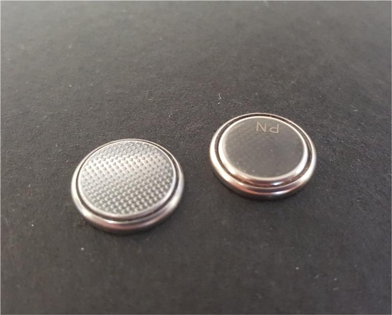
I have done some thorough testing of the battery holders on the original v0.3 boards and the new v0.4 boards and found that it’s the texture of the bottom of the battery that makes the difference. It appears that one brand of battery might have some problems making good contact with the board, but this isn’t limited to the Mayfly. I tested 3 different brands of batteries and I found that one of them is almost smooth of the bottom, whereas the other two have a bumpy texture in the metal. See the attached photo for a comparison between two of them.
What I found was that the smooth-bottom battery sometimes has trouble making good contact when inserted into the Mayfly battery socket. I inserted the bumpy-bottom battery into over 100 Mayfly boards and every one of them worked perfectly. I also had trouble with the smooth battery in a few other devices that were not made by us, so I think the problem is caused by the battery and not specifically the Mayfly board. In every case where the battery wouldn’t make contact, putting a small bit of solder on either the battery or on the board under the holder immediately fixed the connection issue.
Attachments:
-
-
AuthorPosts
- You must be logged in to reply to this topic.