
Features of the EnviroDIY Mayfly Data Logger v1.0 & v1.1
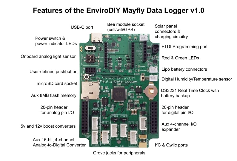
The USB-C port is used to program the Mayfly via your computer. Once the board has been programmed, you can also supply power to the Mayfly with any USB-C cable or mobile phone charger that provides 5vDC.
The Bee socket is compatible with any module that use the standard Bee connection footprint. Modules include Digi Xbee radio modules or EnviroDIY cellular modules, WiFi/Bluetooth, or GPS boards. White and Blue LEDs indicate board power and network status.
A 6-pin header is available for programming the board via a standard FTDI interface board or programming cable. Be sure to observe the polarity and connect the FTDI adapter in the right orientation.
A 6-volt solar panel can be connected to one of the SOLAR sockets for charging a standard 3.7v LiPo battery. A yellow LED will light up whenever there is sufficient sunlight to charge the battery.
Two LEDs (one green, one red) are connected to pins D8 (green) and D9 (red) for full user control.
Dedicated LEDs for board power and external USB power status, which are controlled by DIP switches.
Two JST connectors are labeled LiPo (lithium polymer) battery power connections. Connect a standard 3.7v LiPo battery to either port. You should only connect one battery to the Mayfly. The second port is for older accessory devices like the GPRSbee or LTEbeeAdapter that needed a direct connection to the battery.
The DS3231 Real Time Clock chip needs a small battery to keep it’s clock running when the Mayfly isn’t powered by a main battery. Insert a CR1220 3v lithium battery (with the + side facing up). This battery will last several years under normal use. Users who don’t want to keep the RTC backed up can omit the battery.
Two new onboard sensors: SHT40 digital humidity/temperature sensor and an ALS-PT19 Analog light sensor.
Two 20-pin headers with standard 0.1″ pin spacing provide access to all of the available digital, analog, and power pins. Caution: some of the pin assignments have change between version 0.5b and the new 1.0 board. Mayfly or external devices may be damaged if you use older accessories with the new Mayfly board. See schematic for more details.
Two voltage boost circuits provide 5-volt and a 12-volt supplies that can be switched on or off by using pin D22. This pin is also used to turn the “3.3v_Switched” output on or off. The 12-volt supply can also be changed to 9v if desired. Note: the 12v source of the Mayfly v1.0 boards may not be compatible with some sensors that use wiper motors or high current. The Mayfly v1.1 has higher 12v current output (~100mA), but nominal voltage is ~11.3v. Both the v1.0 and v1.1 boards can supply 5v at approximately 300mA.
Grove connectors provide easy interface to all available digital pins. Four of the connectors contain digital pins (5-6, 4-7, 4-7, and 10-11) and there’s a dedicated Grove connector for I2C protocol. Power on/off for the Grove jacks is controlled by pin D22 as described in the above paragraph, and the voltage levels for each Grove jack are selected by jumper pins next to each jack.
Two more Grove connectors interface with the ADS1115 auxiliary 16-bit A/D converter.
Two QWIIC ports are provided for connection of QWIIC devices (an easy-to-use ecosystem of I2C devices and accessories).
The memory data card socket on the Mayfly accepts standard microSD memory cards.
Onboard 8MB flash memory chip (non-removable) for additional memory storage or saving board configuration files.
PCA9536 I/O expander chip for 4 additional I/O pins in the right-hand 20-pin header.
A small 2×4 header allows users to connect the custom Mayfly microSD right-angle adapter board. This handy accessory allows you to easily access the memory card when the Mayfly is mounted in an enclosure where the usual horizontal slot is inaccessible. Note: Do not use a memory card in both sockets at the same time.
The pushbutton is connected to digital pin D21. Users can have their sketch look for a state change on that pin to provide input to the system.