A few months ago I was asked by a researcher here at the Stroud Water Research Center to come up with an automated way to measure the voltage of 8 fuel cells. The cells need to be electrically isolated from each other, so that requires differential measurements instead of the more common method of using a common ground for everything and then just doing single-ended measurements. I looked into commercial options for measuring 8 differential pairs, but everything I found was either too expensive if you wanted on-board storage and standalone operation, or the cheaper options had simpler hardware but required a dedicated computer to do the actual data collection
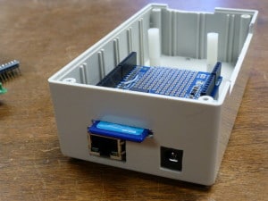
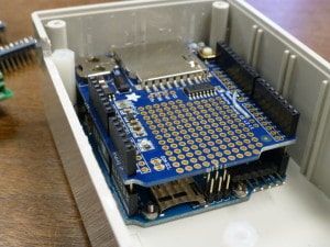
Since I already have an online MySQL database for collecting our streaming dataloggers, I decided to base this data acquisition (DAQ) system on an Arduino Uno Ethernet. At $65, it’s a inexpensive and easy way to build an sensor-interfacing system with the added benefit of being able to send the data via the internet. I also used an Adafruit datalogger shield because it has it’s own realtime clock and SD card slot. With these two features, the DAQ can operate without an internet connection because it will always know what time it is and can store the data on the SD card.
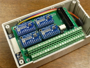
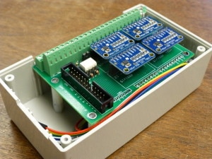
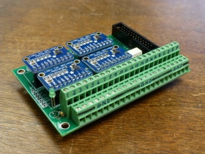
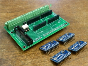
For the actual voltage measurements, I chose the Adafruit ADS1015 12-bit ADC breakout board. These boards are great because they can do 4 single-ended measurements or 2 differential. They also can be assigned 4 different I2C address allowing 4 boards to be connected to the same I2C bus. This gave me the 8 differential measurement pairs I needed, and because I used header sockets on the boards, it also gives me the flexibility to swap out these boards for the ADS1115 boards if I want 16-bit resolution later.
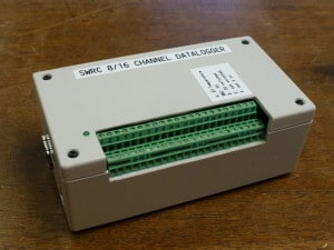
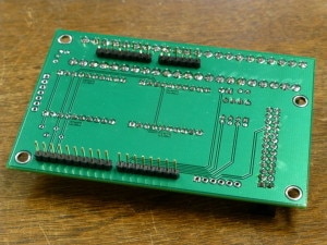
The shield on the top is mainly to break out the pins of the ADC boards to the screw terminals. I also added a ribbon cable header socket for the ADC pins, a dual opto-isolator for controlling switched 5v or external power for optional sensors, and a connection for a DS18B20 digital temperature sensor. It all fit inside an enclosure that I carefully selected to make sure the top row of the screw terminals was flush with the lid, but was large enough inside to fit all the boards when stacked together.
The total cost for everything was around $250, and took about a week from start to finish, thanks to the great service and fast shipping of Adafruit, and the quick production of the PCB boards I got from ExpressPCB. The system has been running non-stop for the past two months and has been recording and uploading the data to our database system where we graph the live data.

 Welcome to EnviroDIY, a community for do-it-yourself environmental science and monitoring. EnviroDIY is part of
Hey nice article. Thanks for posting.
I’m curious – what sort of target voltages where you measuring and what measurement accuracy where you looking for? and over what temperature range. ?
The ADS1015 ADC has a programmable gain so I since I was looking at signals I knew were below 2v, I used the GAIN_TWO setting to give me a range of +/-2.048V. You can select anything from a gain of two-thirds to 16, which is a range of around 6v (but realistically Vcc of 5v for an Uno) down to 0.25v.
For accuracy, the error is supposedly less than one LSB and very stable across the -40 to 120 degree operating range. Years ago I found that the Arduino’s on-board ADC is horribly inaccurate during either extremely hot or cold temperatures in the dataloggers we deployed outside, so we started using the ADS1015 in all of our loggers and have been extremely happy with their performance.
Nice – The ADS1015 handles a lot.
A lot of onboard ADCs need careful looking at – they are improving.
Numbers need confidence/traceability analysis, the errors typically need all adding, the Vref error, temperature drift error across temperature range, the ADC error, and then any external circuitry – so that was why I was curious as to how you were checking it out.
I’m on the Nerds4Natrure.org Maker Fair San Mateo May15 and going to be showing/discussing errors and traceability for depth measuring sensors
http://blog.nerdsfornature.org/post/115703686099/nature-nerds-maker-faire-2015