Home › Forums › Environmental Sensors › Need Help with Clarivue10 Turbidity Sensors › Reply To: Need Help with Clarivue10 Turbidity Sensors
I spent the entire weekend trying to recreate the SDI-12 communication issue with the ClariVue sensors by placing a bunch of Mayfly loggers and turbidity sensors in my freezer and refrigerator in various combinations. I was able to isolate the problem to the Mayfly v1.1 boards not being able to produce sufficient instantaneous current at 12 volts when the ClariVue is first powered up when Mayfly board temperatures are below approximately 5 degrees C. The exact temperature depended slightly on the individual Mayfly board, but more important was the version of the ClariVue sensor. We have some that were made last year and some the were made about a month ago, and I found that the power requirements and timing of the SDI-12 commands were slightly different between the two.
Even at room temperature, I found that some of the measurement commands to the sensor weren’t always successful with the warmup and measurement times as originally defined in the CampbellClariVUE10.h file (5.5 seconds and 9.5 seconds, respectively). Changing them to 8 seconds and 11 seconds resulted in 100% success rate at room temperatures (and all the way down to -20C with the sensor powered by an external source). I just updated the .h file on Github, but you can simply edit your existing file with a basic text editor (not Word) to change the warmup time in line 88 from 5500 to 8000 (remember that Arduino code uses milliseconds to denote time intervals), and change the measurement time in line 99 from 9500 to 11000.
But to address the sensor power issue, we will be revising the 5-volt and 12-volt circuitry on future Mayfly board versions to switch back to the original design that worked in prototype testing a few years ago but couldn’t be implemented into full production because of semiconductor shortage problems at that time. We’ve still got a bunch of those prototypes deployed and powering high-current 12-volt sensors with no problems, it was just unfortunate that we weren’t able to use those parts in the board production because they were impossible to buy for the past 2 years.
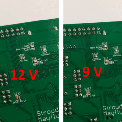
In the meantime, you can easily modify your Mayfly v1.1 boards to generate 9 volts instead of 12 volts, and I tested all of our ClariVue sensors and various Mayfly v1.1 boards using this 9-volt setting and had no trouble powering and communicating with the sensor from -20C to +30C. On the back of the Mayfly board, there’s a solder jumper labeled SJ25 that says “12v/9v”. It’s default position as shipped from us is open, meaning you’ll see two little separate gold pads. You just have to bridge those two pads together with a tiny blob of solder to configure the board’s circuitry to generate 9V instead of 12V. So on the front of the Mayfly board, with the pin jumper next to a SDI-12 Grove jack set to the 12V, you’ll actually get 9V there, and your ClariVue sensor should still work fine and continue to communicate with the Mayfly even if the Mayfly air temp goes way below freezing. I’ve included a photo showing what the back of the Mayfly board should look like once you’ve put a solder blob on the SJ25 pads to enable the 9-volt setting.

 Welcome to EnviroDIY, a community for do-it-yourself environmental science and monitoring. EnviroDIY is part of