Home › Forums › Environmental Sensors › Sensor Values Unrealistic and Unchanging
Tagged: data, logging, mayfly data logger, monitor my watershed, sensors, setup
- This topic has 1 reply, 2 voices, and was last updated 2024-04-14 at 7:30 PM by
 Shannon Hicks.
-
AuthorPosts
-
-
2024-04-14 at 11:06 AM #18421
Hello,
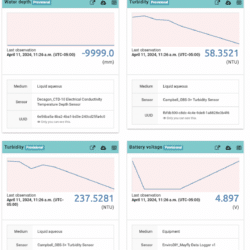
Before installing my system outdoors, I ran a test with my sensors. However, the data I received did not change over the logging interval and seem highly incorrect to me. I have attached a screenshot from Monitor my Watershed on this post. Please let me know if you know of any ways that could help me to fix this issue.
Thank you so much for the help!
Attachments:
-
2024-04-14 at 7:30 PM #18423
Sensor values of -9999 for the Hyrdos21 CTD sensor mean that the Mayfly board isn’t hearing any communication from the sensor. Did you carefully follow all the directions in the Monitoring Station Manual (specifically section 6) for preparing and programming a Mayfly for use with the Hydros21? The sensor’s default SDI12 channel number needs to be changed from 0 to 1 (if you’re using one of our example ModularSensor sketches), and it must be connected securely to the 3.5mm headphone jack and connected to one of the Grove jacks labeled SDI-12. If you’re using a bare-wire CTD sensor, then doublecheck that you’ve got the appropriately-colored wires connected to the right terminals of the screw terminal adapter board (for power, data, and ground).
And the OBS-3 turbidity sensor doesn’t appear to be connected either, because with no sensor connected the low range value is usually around 60NTU and the high range is around 250NTU. The online Monitoring Station Manual doesn’t show instructions for how to connect an OBS-3 sensor anymore because they were discontinued 4 years ago. You’ll need either our old-style 6-terminal screw adapter board, or our newer multipurpose 6-terminal adapter board. That board gets connected to the Mayfly via the AA0-AA1 aux analog Grove jack. The wiring colors on the OBS-3 cable should be green, black, and shield all connected to ground. Red connected to 5V (be sure to move the voltage-selection jumper next to the Aux Analog Grove jacks to the 5v position (it ships in the default 3v position). The blue wires goes to D1 (or S1), and the white wire goes to D2 (or S2). If you’re using the newer multipurpose screw terminal adapter board, be sure the 3 solder jumpers on the back of the adapter board are soldered in the DEFAULT position (as shown in on of the product photos on the shop page for the adapter: https://www.envirodiy.org/product/envirodiy-grove-6-pin-screw-terminal-adapter-pack-of-5/)
-
-
AuthorPosts
- You must be logged in to reply to this topic.

 Welcome to EnviroDIY, a community for do-it-yourself environmental science and monitoring. EnviroDIY is part of