Home › Forums › Mayfly Data Logger › Reading -9999 on all Sensors
- This topic has 11 replies, 2 voices, and was last updated 2024-12-05 at 9:24 AM by
 Shannon Hicks.
-
AuthorPosts
-
-
2024-11-11 at 4:00 PM #18733
Hello, I’ve recently been working on programming the MayFly data logger. After completing the code (or what I thought was completing the code) and connecting it to MonitorMyWatershed, I am reading -9999 from both the ClariVUE 10 sensor and the Hydros 21. I believe that both are physically connected properly. I think that it might be an issue regarding setting the channels, as when I run the test codes I have found online all spots say vacant. Can someone please provide guidance or the proper code to use to set the channels if this is believed to be the actual issue? I have attached the zip file of my code and the file I was using to try and change the address.
Attachments:
-
2024-11-11 at 4:48 PM #18736
Both of those sensor models ship from their manufacturers with their SDI12 address set to ‘0’ (zero). In order for the Hydros21 sensor to work with the Mayfly logger in SDI12 mode, you MUST change the address of the sensor to anything other than zero (otherwise the sensors is in TTL output and not SDI12). It’s okay for the ClariVue sensor to remain at channel 0, but your logging sketch should agree with whatever you’ve set it to, and your sketch says 2, so you’ll need to use the address-changing sketch to set the channels. Note that you can’t connect both new sensors at the same time when setting the channel. Only connect one sensor to the Mayfly when doing the address changing procedure. Once you’ve got one sensor connected, the sketch will cycle though all 62 possible channels. If it’s not stopping on zero (or maybe another channel if you’ve been able to successfully change the channel earlier), then that means your logger doesn’t hear anything from the sensor. If that’s the case, then your wiring to the Mayfly may be wrong or something else. Are you supplying 12v to the ClariVue sensor using a screw terminal board (either directly from the Mayfly’s onboard 12v option or the external 12-v boost screw terminal board)? The Hydros21 works fine at 3.3v or 5v or 12v. If you’re using the 3.5mm stereo plug option, make sure it’s plugged firmly into the jack on the Grove adapter board. If you’re using bare wires, make sure you’ve got the 3 wires from the sensor connected to the proper screw terminals (Ground, V+, and S2).
-
2024-11-11 at 8:46 PM #18739
Thank you so much for the quick response! Could you detail how to make sure we are supplying the 12v to the ClariVue? That being said I am still a bit confused as to why the Hydros 21 would read as vacant when it is the only sensor connected during testing and it would run regardless of the voltage.
-
2024-11-12 at 2:26 PM #18740
Can you describe how you’ve connected the sensors to your Mayfly, there are multiple ways to do it correctly with the adapters we offer and even more if you’re doing it a non-traditional way. Better yet, could you take a pictures of your setup showing how you’ve connect each of the sensors to the Mayfly?
-
-
2024-11-13 at 4:04 PM #18744
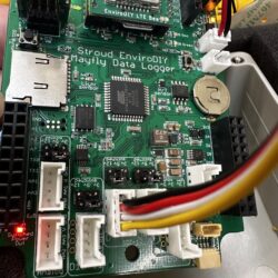
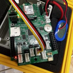
Here are a few pictures of our setup.
-
2024-11-14 at 6:26 PM #18749
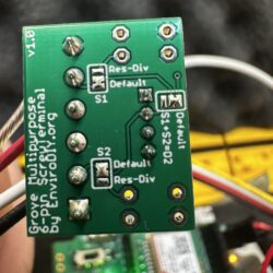
In your 4th picture, it looks like the Grove cable plug may not fully be seated in the grove jack. Not sure about any of the other ones since the angles in the photos didn’t show them well, but be sure that it’s pressed all the way into the jack. And your second photo shows that your two SDI12 Grove jack voltage selection jumpers are both set to the default 3.3v position. As stated above, the ClariVue sensor requires 12v to operate, and since you’re not using one of the 12v boost screw terminal boards, (photo 3 shows the standard 6-position multipurpose screw terminal board), then you’ve got to select 12v on the Grove jack where you’ve got the turbidity sensor connected. Also look at the bottom of the screw terminal board and make sure there are solder blobs on the 3 solder jumpers, all in the default position (there’s a photo of the bottom of the board on the product page, showing the 3 possible solder jumper positions)
I assume you plugged both sensors into the Mayfly for the photo, but remember that you need to fully disconnect one of them if you’re trying to set the SDI12 channel. The sketch you sent looks like it’s been slightly modified from the original one that’s included in the SDI12 library’s example (which can be found here: https://github.com/EnviroDIY/Arduino-SDI-12/blob/master/examples/b_address_change/b_address_change.ino). I would recommend you use the original sketch, with only one sensor attached, making sure both ends of the Grove cable are plugged in securely, and that you use 12v on the one for the turbidity sensor.
-
2024-11-19 at 2:23 PM #18751
Hello, we’ve returned to try and set up the two sensors again but are still running into the issues of both being vacant at every location. We have tried both of them individually and have changed the 3.3v position to the 12v position for the Clarivue sensor. The Hydros is still connected to the 3.3v. We have also changed the sketch for the channel as you suggested. I am attaching pictures of what we have so far up to this point after your suggestions, but we are finding it odd that even the Hydros would show up vacant if the voltage does not matter.
-
2024-11-19 at 5:36 PM #18756
Have you tried measuring the voltage being applied to the sensors by using a voltmeter when the channel scanning sketch is running? For the turbidity sensor’s screw terminal board, put the voltmeter’s red probe on either of the V+ screws, and the black probe on either of the GND screws. For the CTD sensor’s 3.5mm headphone jack adapter board put the probes on the two points shown in the attached photo.
Attachments:
-
2024-12-03 at 2:56 PM #18775
Hi Shannon, thank you again. We were finally able to get a voltmeter and test the connection. There is voltage being applied to the sensors when the channel scanning sketch is running, but the program still says no sensor detected and to check the physical connection. We have tested both sensors. Could there be an issue with continuity? We have our data point at 7 and our power at 22, just making sure that is correct as well.
-
2024-12-03 at 9:28 PM #18776
Do you happen to have a spare Mayfly board, or any other Arduino-type board that you could run the sketch on?
-
2024-12-04 at 2:00 PM #18777
Unfortunately, we do not have any other boards. Would it be worth it to purchase a new one? Or is there more troubleshooting we could do with the current setup?
-
2024-12-05 at 9:24 AM #18780
Can you email me at mayfly@envirodiy.org, I have a few other questions about the software libraries and hardware combinations for your setup.
-
-
AuthorPosts
- You must be logged in to reply to this topic.

 Welcome to EnviroDIY, a community for do-it-yourself environmental science and monitoring. EnviroDIY is part of


