-
Anthony Aufdenkampe wrote a new post 8 years ago
In the summer of 2016, Shannon Hicks and other Stroud Water Research Center (SWRC) staff kept busy deploying dozens of sensor stations based on our new EnviroDIY Mayfly Data Logger. Most recently, we collaborated […]

 Welcome to EnviroDIY, a community for do-it-yourself environmental science and monitoring. EnviroDIY is part of WikiWatershed, an initiative of Stroud Water Research Center designed to help people advance knowledge and stewardship of fresh water.
 New to EnviroDIY? Start here

Very nice project!
Do you have an exemple code with the GPRSbee. I use GPRSbee rev6b + stalker V3.1 but I have some problem with the gprsbee.init.
Thank you,
Eric
We’re working on getting an example sketch for the stations shown in this post, using the GPRSbee cell phone wireless ratio. We’re also working on getting as much code as possible in our EnviroDIY GitHub code repository for the Mayfly: https://github.com/EnviroDIY/EnviroDIY_Mayfly_Logger
Stay tuned!
This might be helpful: http://forum.sodaq.com/t/gprsbee-library/471
Dear Anthony, congratulations. Based on the pictures, I have following practical questions:
1) What solar panel are you using? The solar panel that comes with the Mayfly is much smaller.
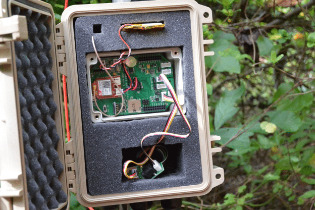
2) Is it acustic material that you use to fill up the space in the box? Has it any other function?
With friendly greetings,
Arnoud
The solar panels in the photos above are made by a company called Voltaic Systems (https://www.voltaicsystems.com/solar-panels). They have a variety of sizes, we prefer the 2W for sunny areas, and 3.5W for shady areas. T he small 0.5w panel that comes with the Mayfly starter kit is not waterproof, but it’s handy if you want to build a small logger and put the panel inside the clear lid of the small Mayfly enclosure.
The Pelican cases we use for our loggers come with foam already inside them, so you simply cut away part of the foam to create spaces for the logger, battery, cables, etc.
That looks very nice. Did you have any ESD-problems with that foam and those cases? I’ve tried to use some fake pelican boxes (made of PE plastic I belive) as enclosures for electronics and had huge problems; as soon as I came close to the box the electronics went crazy.
No, I haven’t had any problems with the foam or the cases. In fact, in some of the loggers in locations with a strong cellular signal, I skip the external antenna for the GPRS module and simply use a small PCB antenna and simply tuck that antenna between the small Mayfly enclosure and the foam.
HI, do you have a diagram or wiring map so I can understand how to connect the OBS sensor to the mayfly data logger please?
Hi @walterartavia02gmail-com,
I haven’t deployed an OBS, but it looks like it goes into the I2C port using the instructions at:
https://github.com/EnviroDIY/ModularSensors#campbell-scientific-obs-3
where it says that, “The power supply is connected to the red wire, low range output comes from the blue wire, high range output comes from the white wire, and the black, green, and silver/unshielded wires should all be connected to ground.”
Beth, thanks for sending Walter the links to the sensor description in the Modular Sensors library ReadMe file! That is a great resource.
One important correction, the Campbell Sci. OBS3+ sensor is an ANALOG sensor, and therefore should be connected to one of the Aux Analog grove ports on the Mayfly’s lower left side. The Auxiliary Analog-to-Digital Converter (ADC) chip is, however, an I2C device, which is why the description mentions I2C.
Walter, if you read that ModularSensors sensor description carefully, you’ll also see that the OBS3+ works better with 5V of power, so you should move the power jumper on the Mayfly for the Aux Analog from switched 3.3V to switched 5V.
Thanks a lot Anthony / Fisherba, I will work on the MayFly and the OBS on the weekend!.
Hi fisherba, thanks a lot for the help, as soon I arrive to my office will work on it. I will like to ask you if you had work with any turbidity sensor in special?, I’m looking to deploy at last 14 of those sensor spread out in fresh water tanks.
Hi @walterartavia02gmail-com, I completely missed this turbidity question. We have used Yosimetech (http://www.yosemitech.com/en/) turbidity sensors, but there’s enough hassle in ordering (customs hang-ups every time) and creating a RS-485 shield to communicate with those, that going with the Campbell sensor might be in my future.