Forum Replies Created
-
AuthorPosts
-
Okay, thank you Shannon! I have a follow-up question. So when using the AuxAnalog pins, from my understanding you have to multiply the digital signal by 0.1875 to convert it to a millivolt reading. Would you need to do the same if you were to use the other analog pins (A0, A1, ,etc.), or is the 0.1875 value unique to the ADS1115 ADC?
How do the analog pins found on the 20-pin header (pins A0, A1, A2, etc.) differ in function and purpose from the auxiliary analog pins (AA0, AA1, etc.)? From what I’ve seen, you need to connect analog sensors to the auxiliary analog pins and use an Adafruit library to get the millivolt readings because of an ADC they are connected to. I’ve successfully done this, and it has worked great, but I guess I’m curious what the other analog pins (A0, A1, etc.) on the 20-pin header are used for and what type of sensor outputs would be used on them.
2023-05-09 at 2:27 PM in reply to: Negative Voltage Reading from Single-ended ADC Using Apogee SP-212-SS Sensor #17803Okay sounds good. I was also wondering, Shannon, if you might be able to help me out with something. I’m looking to attach a suite of sensors to the Mayfly that have a mixture of analog outputs and digital outputs. I’m worried that I won’t be able to get all the sensors I need with this data logger. Is this something I could talk through with you? I can do a separate forum post, or I could correspond over email. Either way, I would just like your input on how to best approach the situation. The main things I’m looking at are not having enough ADC pins and using Modbus with the Mayfly. If you can help that’d be great! I’d love to use the Mayfly for the environmental sensing stations I am setting up with the Utah Water Research Laboratory.
2023-05-08 at 11:48 AM in reply to: Negative Voltage Reading from Single-ended ADC Using Apogee SP-212-SS Sensor #17791Thank you for your reply! That definitely helped. I think the only thing I’m still confused on is the output channel. You mentioned that the white wire in the uppermost grove jack is connected to analog channel zero, but when I look at the board, the label next to that wire is AA1. If you could clear that up for me that would be great. Thanks for the help!
How do I switch over to the 12 volt power supply? The Board Features Overview page says the 5 and 12 volt circuits can be accessed from pin D22, but I am having trouble finding that pin. I notice there are some pins labeled Sw3, Sw5, and Sw12 at the bottom of the 20-pin headers. Is that where I switch the supply voltage, and if so, which pins am I connecting? I am also a little confused on how the jumper pins that sit at the head of the grove terminals work. Do I need to move the jumper pin for the grove terminal I plug into if I switch the power supply? Thanks!
It is working now! Thank you for helping me through that!
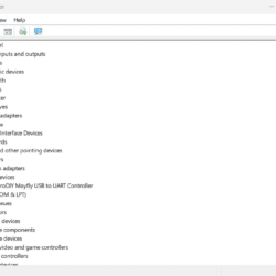
I have swapped out the cable for one that has transmitted data for other devices and I am getting the same thing. My board receives power, but it doesn’t talk with my computer. The attached picture is what shows up on my device manager when I plug it in.
Attachments:
-
AuthorPosts

 Welcome to EnviroDIY, a community for do-it-yourself environmental science and monitoring. EnviroDIY is part of