Forum Replies Created
-
AuthorPosts
-
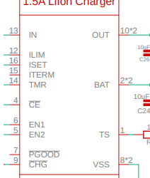
I don’t have a ton of experience reading schematics, so I could be in error here. But FYI, it appears there may be an inconsistency in the v1.1 rev A schematic regarding the part number of the LiIon Charger chip. Please see attached screenshot. (Also understanding that these things are a moving target as chip availability changes.)
-Matt
Attachments:
FYI, just noting here that the Hardware Status and Availability page is not up to date, at least with respect to Mayfly board availability on Amazon, as they are out of stock.
I’ve confirmed that the Verizon SIM we used was this one, from NimbeLink:
https://www.digikey.com/en/products/detail/nimbelink-llc/NL-SIM-VER-M1/7101751@jamesbailey I’ll check with my colleague to find out exactly which SIM he used for the test; he’s in the field for a few days. My test code is based on https://github.com/EnviroDIY/ModularSensors/blob/master/examples/DRWI_SIM7080LTE/DRWI_SIM7080LTE.ino, and the only modem-related code change I made was to the APN.
-Matt
Hi @neilh20, I believe the SIM we used was a RevX.
The SIMCom 7080G modem chip upon which the EnviroDIY LTE Bee is built did not have Verizon certification until early August. Once they notified me, I asked SIMCom support what APN setting to use for Verizon, and this was their response:
Set you APN as follows:
at+cgdcont=1,”ipv4v6”,””
at+cgdcont=2,”ipv4v6”,”vzwadmin”
at+cgdcont=3,”ipv4v6”,”vzwinternet”We were able to get an EnviroDIY LTE Bee to connect to Verizon, using ModularSensors, by setting the apn to an empty string, e.g.:
12// Network connection informationconst char* apn = "";Hopefully this helps anyone else who needs Verizon coverage with these newer modems.
Best,
MattOK, got it, thanks.
I’ve made the hardware and software modifications you recommended and all seems to work perfectly.
Thanks again.
Thanks for this excellent detail.
So we could continue to use the LTEBee adapter with the Digi modem on a v1.1 Mayfly, which would retain the functionality of the white and blue modem status LEDs, and would connect the Bee socket’s pin to the proper status pin on the Digi (without need to modify SJ19), and we would not need the power jumper to the Lipo socket. Is that correct?
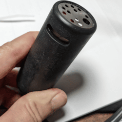
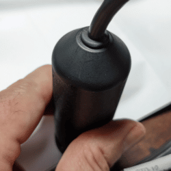
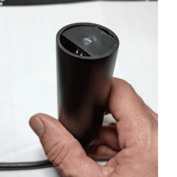
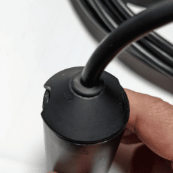
A couple bits of additional info. To visually identify whether your Hydros 21 is a Gen 1 or a Gen 2, see attached photos of the sensor head on each version. Note that some Gen 1’s had red cables, but not all.
Second, as Shannon noted in the post she linked to above, the address-setting on the Gen 2 is slightly more finicky; you just have to repeat it a few times. Here’s my serial output from the b_address_change.ino sketch:
12345678910111213141516171819202122Opening SDI-12 bus...Powering up sensors...Checking address 0...VacantVacantVacantChecking address 1...VacantOccupiedSensor active at address 1.Enter new address.Readdressing sensor.Success. Rescanning for verification.Checking address 0...OccupiedSensor active at address 0.Enter new address.Readdressing sensor.Success. Rescanning for verification.Checking address 0...VacantVacantVacantChecking address 1...OccupiedSensor active at address 1.Enter new address.Note the “Checking address 1…Vacant
Occupied”. Then after the first “Enter new address” prompt, I typed 1, but it came back with “address 0…Occupied”. So be persistent and your change will take.-Matt
That was it – thanks!
-Matt
-
AuthorPosts

 Welcome to EnviroDIY, a community for do-it-yourself environmental science and monitoring. EnviroDIY is part of