Forum Replies Created
-
AuthorPosts
-
We’ve just had a failure to communicate with our newest Hydros 21 sensors (likely Gen 2). While I’ve had success setting the address with the b_address_change sketch, my standard Mayfly code can’t talk to the sensor and returns values of -9999. It looks to me like the SDI-12 library has not changed since May 2021 (https://github.com/EnviroDIY/Arduino-SDI-12/).
However, MeterHydros21.h within ModularSensors was updated last month (https://github.com/EnviroDIY/ModularSensors/tree/master/src/sensors) for the new timing requirements of the Gen 2 Hydros 21, and updating that library was what fixed the communication problems I was having.
These were just deployed 3 days ago and have been doing this from the beginning.
We are also seeing the missing display of “Last observation” values for all new stations we deploy, though it continues to work for stations that were deployed prior to the MonitorMyWatershed release on December 7th.
I’m also unable to delete sites (Server Error 500), and unable to delete sensors (no errors, but nothing gets deleted). I am going to report this via an issue at the Github site for the MMW data portal:
https://github.com/ODM2/ODM2DataSharingPortal/issuesVery helpful to know. Thanks for sharing, James.
Matt
Thanks for the schematic – that is helpful. I removed the solder blob using solder wick and re-added it to the res-div position, but it wasn’t pretty; it looks like I overheated the board a bit, but it still works. Later, I found a different technique in this video, which I’ll share here for anyone else who needs it.
FYI, Turner tech support tells me that Signal Ground and Supply Ground must be “Kept separate so that noise isn’t injected into the response.”
Thanks Shannon. I’m not positive that I need to use differential measurement… I’m approaching the edge of my knowledge as a non-EE. Turner doesn’t specify whether it’s OK to connect signal and power grounds to the same point — maybe I’ll ask their tech support. But when the sensor is on, I’m measuring around 13 mV between its signal ground and power supply ground wires. Thus when I read the measured value (voltage) across Sig+ to Sig-, it’s different than if I read voltage across Sig+ to Supply-.
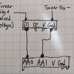
I just now modified a Grove cable by disconnecting the V and Gnd lines and moving the Signal Ground so that it will connect appropriately to the ADC (see ugly drawing attached), and will test it today. I found it pretty easy to disconnect individual wires from a Grove connector, using a dental pick, so I may just go that route.
Matt
Attachments:
After probing the screw term adapter, I don’t think that it will work for my purposes as I described above. If I’m correct, the way the adapter’s voltage divider works is this: When the S1 jumper is set to Res-Div and two matched resistors are installed on the S1 side of the adapter, the voltage output on the Grove’s D1 pin will be half of the voltage input to screw terminal S1, with Gnd as reference.
However, because my sensor’s output is referenced to its Signal Ground lead, not its Supply Ground, I need to use the ADC’s differential, rather than single-ended, signaling capability. Because of the way the screw terminal adapter maps the output and ground pins, I don’t believe I can use its resister-divider capability for differential signals. Any suggestions? @shicks?
For reference, the sensor’s wiring guide is here: http://docs.turnerdesigns.com/t2/doc/manuals/998-2188.pdf
Thanks,
Matt
-
AuthorPosts

 Welcome to EnviroDIY, a community for do-it-yourself environmental science and monitoring. EnviroDIY is part of