Forum Replies Created
-
AuthorPosts
-
Thanks @aufdenkampe – really appreciate that update, and all of the hard work by you and the team to fix and document these issues!
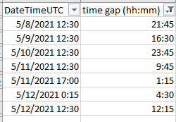
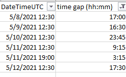
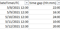
Note that the lost data appears to extend beyond May 7th, with very large data gaps each day from the 8th through 12th. The images attached below show these data gaps for 3 of our sites, with the UTC timestamp when datapoints resumed and the duration of each outage. I’m assuming these data are lost too.(?)
Matt
Attachments:
We are also seeing the data gaps that I believe @thomas-schanandore and @movingplaid have reported above across all 3 of the stations that I’ve checked.
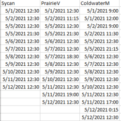
In particular, there are large gaps (9- to 24-hours) every day since at least May 5th, followed by data resuming at 12:30UTC across every station. This suggests that something is failing on the server and that an intervention is being done to fix/restart it every day sometime shortly before 12:30UTC.
I’m attaching a screenshot that shows the UTC timestamps marking the end of each data gap since May 1st for 3 of our stations, where the data gap is of duration greater than 1 hour.
Matt
Attachments:
Hi All,
Just checking in to see if there is any news about the status of MMW. I haven’t been able to find relevant issues in the ODM2 Github site, so thought I’d share here what we’re seeing on MMW:
- The big Download Sensor Data button returns a Server Error (500).
- No sparkline plots are displayed.
- The 3 buttons for each variable are disabled: Open in TSA, Download, and View Table.
- Site Alerts are being sent out by MMW for all our sites, though the data is apparently getting uploaded.
- TSA won’t display charts beyond the morning of 5/1 UTC (e.g. Bear Creek).
Thanks,
Matt
Trout Unlimited
Hi Dan,
I’m curious whether it’s possible to identify Gen 1 vs Gen 2 Hydros21; are they labeled? I’m wondering what I’ve got.
Thanks,
Matt
Ok, I see. Thanks so much for taking the time to provide all these details – very helpful!
Best,
MattTrout Unlimited
Thank you both for those details!
So to be clear: if I have only 1 SDI-12 sensor on the bus, and it’s at address 0, it should work properly with ModularSensors, even if I’m averaging 6 readings and collecting conductivity, temp, and depth each time. Is that correct?
Thanks Anthony. That warning is pretty clear. But I wonder why that’s a constraint.
It looks like “0” is a valid address according to the SDI-12 spec, and Meter supports it. Perhaps there’s something in ModularSensors that doesn’t like it. Scanning through the code, I don’t see anything right off.
Matt
@srgdamiano
Hi Sara, any advice on the question above, about powerUp/powerDown vs. wake/sleep?Matt
Thanks to both of you for your responses! I think I had just figured out the cause of my problem right about the time you were posting them, but needed to continue refining and testing my code before replying.
What’s working now is:
- In the sensor’s setup() function, set trigger pin to an output
- at powerUp(), set pin HIGH
- at wake(), run the wiper (set pin LOW, wait 50ms, set pin HIGH)
- at powerDown(), set pin LOW
The wiper cycles as expected and sleep current is <0.7mA. The only exception seems to be that when the Mayfly wakes up at the first measurement cycle (not at startup), the wiper doesn’t run as expected. At all subsequent measurement cycles that I’ve watched, the wiper cycles properly.
@srgdamiano Sara, which of the following functions would you recommend as a best practice for where to change the pin value described above, at powerUp and powerDown, or at wake and sleep?
@neilh20 That’s funny on the FTDI cable (well, funny in hindsight) – ouch!Best,
MattTrying to track down and eliminate my my Mayfly’s excessive power draw during sleep, I rebuilt my circuit to use the Mayfly’s onboard ADS1115 via voltage dividers, but got the same results; my sleep current is still around 6 mA. However, I discovered that if I disconnect the Turner’s wiper trigger wire from D10, sleep current drops to around 0.5mA.
To initiate the Turner’s wiper cycle, you pulse its trigger line low for 50 milliseconds. My TurnerTurbidityPlus class (code below) derives from Sensor, and its setup() method sets the D10 pin high; then when it’s time for a measurement, its wake() function sets D10 low, delays 50 milliseconds, and sets it back to high. Is this code causing the current drain, and how can I eliminate it?
-Matt
123456789101112131415161718192021222324252627282930313233343536373839404142434445464748495051525354555657585960616263646566676869707172737475767778798081828384858687888990919293949596979899100101102103104105106107108109110111112113114115116117118119120121122123124125126127128129130131132133134135136137138139140141142143144145146147148149/*** @file TurnerTurbidityPlus.cpp* @copyright 2020 Stroud Water Research Center* Part of the EnviroDIY ModularSensors library for Arduino* @author Sara Geleskie Damiano <sdamiano@stroudcenter.org>* Adapted from TurnerCyclops by Matt Barney <mbarney@tu.org>* @brief Implements the TurnerTurbidityPlus class.*/#include "TurnerTurbidityPlus.h"#include <Adafruit_ADS1015.h>// The constructor - need the power pin, the data pin, and the calibration infoTurnerTurbidityPlus::TurnerTurbidityPlus(int8_t powerPin, int8_t wiperTriggerPin, adsDiffMux_t adsDiffMux,float conc_std, float volt_std, float volt_blank,uint8_t i2cAddress, adsGain_t PGA_gain,uint8_t measurementsToAverage, float voltageDividerFactor): Sensor("TurnerTurbidityPlus", TURBIDITY_PLUS_NUM_VARIABLES, TURBIDITY_PLUS_WARM_UP_TIME_MS,TURBIDITY_PLUS_STABILIZATION_TIME_MS, TURBIDITY_PLUS_MEASUREMENT_TIME_MS,powerPin, -1, measurementsToAverage) {_wiperTriggerPin = wiperTriggerPin;_adsDiffMux = adsDiffMux;_conc_std = conc_std;_volt_std = volt_std;_volt_blank = volt_blank;_i2cAddress = i2cAddress;_PGA_gain = PGA_gain;_voltageDividerFactor = voltageDividerFactor;}// DestructorTurnerTurbidityPlus::~TurnerTurbidityPlus() {}String TurnerTurbidityPlus::getSensorLocation(void) {#ifndef MS_USE_ADS1015String sensorLocation = F("ADS1115_0x");#elseString sensorLocation = F("ADS1015_0x");#endifsensorLocation += String(_i2cAddress, HEX);sensorLocation += F("_adsDiffMux");sensorLocation += String(_adsDiffMux);return sensorLocation;}void TurnerTurbidityPlus::runWiper() {// Turner Tubidity Plus wiper requires a 50ms LOW signal pulse to trigger one wiper rotation.// Also note: I was unable to trigger multiple rotations without pausing for ~540ms between them.MS_DBG(F("Initate TurbidityPlus wiper on"), getSensorLocation());digitalWrite(_wiperTriggerPin, LOW);delay(50);digitalWrite(_wiperTriggerPin, HIGH);// It takes ~7.5 sec for a rotation to complete. Wait for that to finish before continuing,// otherwise the sensor will get powered off before wipe completes, and any reading taken// during wiper cycle is invalid.delay(8000);MS_DBG(F("TurbidityPlus wiper cycle should be finished"));}bool TurnerTurbidityPlus::setup(void) {// Set up the wiper trigger pin, which is active-LOW.pinMode(_wiperTriggerPin, OUTPUT);digitalWrite(_wiperTriggerPin, HIGH);return Sensor::setup();}bool TurnerTurbidityPlus::wake(void) {// Run the wiper before taking a readingrunWiper();return Sensor::wake();}bool TurnerTurbidityPlus::addSingleMeasurementResult(void) {// Variables to store the results infloat adcVoltage = -9999;float calibResult = -9999;// Check a measurement was *successfully* started (status bit 6 set)// Only go on to get a result if it wasif (bitRead(_sensorStatus, 6)) {MS_DBG(getSensorNameAndLocation(), F("is reporting:"));// Create an Auxillary ADD object// We create and set up the ADC object here so that each sensor using// the ADC may set the gain appropriately without effecting others.#ifndef MS_USE_ADS1015Adafruit_ADS1115 ads(_i2cAddress); // Use this for the 16-bit version#elseAdafruit_ADS1015 ads(_i2cAddress); // Use this for the 12-bit version#endif// ADS Library default settings:// - TI1115 (16 bit)// - single-shot mode (powers down between conversions)// - 128 samples per second (8ms conversion time)// - 2/3 gain +/- 6.144V range (limited to VDD +0.3V max)// - TI1015 (12 bit)// - single-shot mode (powers down between conversions)// - 1600 samples per second (625µs conversion time)// - 2/3 gain +/- 6.144V range (limited to VDD +0.3V max)ads.setGain(_PGA_gain);// Begin ADCads.begin();// Print out the calibration curveMS_DBG(F(" Input calibration Curve:"), _volt_std, F("V at"), _conc_std,F(". "), _volt_blank, F("V blank."));// Read Analog to Digital Converter (ADC)// Taking this reading includes the 8ms conversion delay.// We're using the ADS1115 library's voltsPerBit() to do the bit-to-volts conversion// for usadcVoltage =ads.readADC_Differential(_adsDiffMux) * ads.voltsPerBit() * _voltageDividerFactor; // Getting the readingMS_DBG(F(" ads.readADC_Differential("), _adsDiffMux, F("):"),String(adcVoltage, 3));// The ADS1X15 outputs a max value corresponding to Vcc + 0.3Vif (adcVoltage < 5.3 && adcVoltage > -0.3) {// Skip results out of range// Apply the unique calibration curve for the given sensorcalibResult = (_conc_std / (_volt_std - _volt_blank)) *(adcVoltage - _volt_blank);MS_DBG(F(" calibResult:"), String(calibResult, 3));} else { // set invalid voltages back to -9999adcVoltage = -9999;}} else {MS_DBG(getSensorNameAndLocation(), F("is not currently measuring!"));}verifyAndAddMeasurementResult(TURBIDITY_PLUS_VAR_NUM, calibResult);verifyAndAddMeasurementResult(TURBIDITY_PLUS_VOLTAGE_VAR_NUM, adcVoltage);// Unset the time stamp for the beginning of this measurement_millisMeasurementRequested = 0;// Unset the status bits for a measurement request (bits 5 & 6)_sensorStatus &= 0b10011111;if (adcVoltage < 5.3 && adcVoltage > -0.3) {return true;} else {return false;}} -
AuthorPosts

 Welcome to EnviroDIY, a community for do-it-yourself environmental science and monitoring. EnviroDIY is part of


