@neilh20
11 days agoForum Replies Created
-
AuthorPosts
-
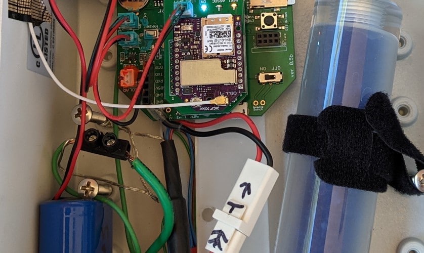
For the solar connecter, I colour the socket and the jack in an acrylic orange so that there is a visual match. The LiIon battery in a cooler blue. Of course have to be careful to only get the acrylic paint on the outside of the jack and not have leak inside. Its not perfect, but provides a little clue.
Attachments:
Suspect Mayfly1.1
The cable I was using also went bad and I’ve marked it as suspect – its a distinctive pink cable. I’ve inspected the Mayfly USB c on Mayfly1.1 with an Eye Loupe, and it is hard to inspect but nothing jumps out, seems OK.
I did have a USB current monitor in the testing before hand, and the current had gone up to 1.2A while charging a 2.2Ahr battery – but difficult to know if it was related. However the Mayfly options are not set to do a high charge, just 0.5A.
I switched to Linux Ubuntu to get more details, and a sturdy USB-C interface and I get with working White Cable into Mayfly1.0
dmesg
[20236.503620] usb 5-1: New USB device strings: Mfr=1, Product=2, SerialNumber=3
[20236.503624] usb 5-1: Product: EnviroDIY Mayfly USB to UART Controller
[20236.503627] usb 5-1: Manufacturer: Silicon Labs
[20236.503630] usb 5-1: SerialNumber: 0001
[20236.565048] usbcore: registered new interface driver usbserial_generic
[20236.565911] usbserial: USB Serial support registered for generic
[20236.586585] usbcore: registered new interface driver cp210x
[20236.586749] usbserial: USB Serial support registered for cp210x
[20236.586863] cp210x 5-1:1.0: cp210x converter detected
[20236.594710] usb 5-1: cp210x converter now attached to ttyUSB0
but then insert into Mayfly1.1 it doesn’t respond on the USB. It does get powered,
I think I have all the switches right, but here is a video https://photos.app.goo.gl/2n43i7qjLGmwbiQz7
My USB connect to a rev1.1 board appears to be failing.
It was working, and now its stop connecting to the PC, stops even causing an audible ding.
If I take the same USB C cable and plug it in to the USB C of a Rev1.0A3 it sometimes works. Usually causes an audible ding, but sometimes doesn’t appear as a com port.
I’ve rebooted my PC twice, and left the Rev1.1 board powered off overnight to see if it might recover.
Just wondering any suggestions for what might be the issue, or way of checking the driver.
I am seeing the boards work through the FTDI connector.
One aspect of measurements the Mayfly does manage is the time. If the small battery gets used up, then it will reset to a default time. Another way of checking time is roughly accurate (+/ couple hours) is when the peak temperature occurs.
I’ve been chewing and reading about LoRa for some time, and just recently been reviewing as part of student engineering project the data flow for LoRa and LoRaWan to TTN (The Things Network) and then to ubidots.
LoRa is designed as a long distance wireless protocol, however its also has constrained packet size.
So it seems to me, at this stage LoRaWan/TTN is incompatible with MMW, as the POST to MMW use UUIDs for variables, which is a lot of overhead.
So for LoRaWan/TTN to MMW, it would need some form of COAP support on the TTN gateway. A way of associating the KEYs and UUID, on the Mayfly, to be transmitted and stored on the TTN gateway.
To phrase it simply, the LoRa packet are small, to allow them to be delivered wirelessly over a long distance. To do that the variable need to be encode into the packet, and then on the TTN gateway decoded from the packet into a JSON format.
The Arduino.Cc offering has some good explanations https://docs.arduino.cc/learn/communication/lorawan-101
Though maybe somebody has figured it out, and we’ll all be pleasantly surprised and amazed

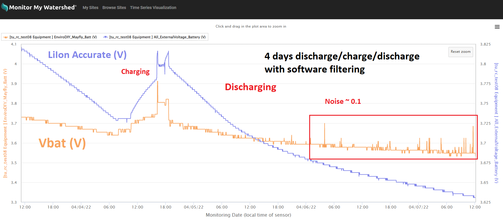
Here are some graphs of measured Vbat(10bit) with a software filtering that I’ve just completed. Its using a 2minute reading sample time – the electronic noise is hopefully similar when used on 15minute sampling intervals.
For the Mayfly 1.1 & Adafruit PkCell 4400mAh, I’ve run it for 4days interfacing over Modbus/RS485 in a critical voltage range of 3.85V dropping 0.2V to 3.65V.
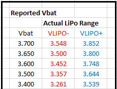
Vbat is under reading the LiIon Voltage by 0.1V, and still having some noise break through during this period of 0.1V, but much better than unfiltered.
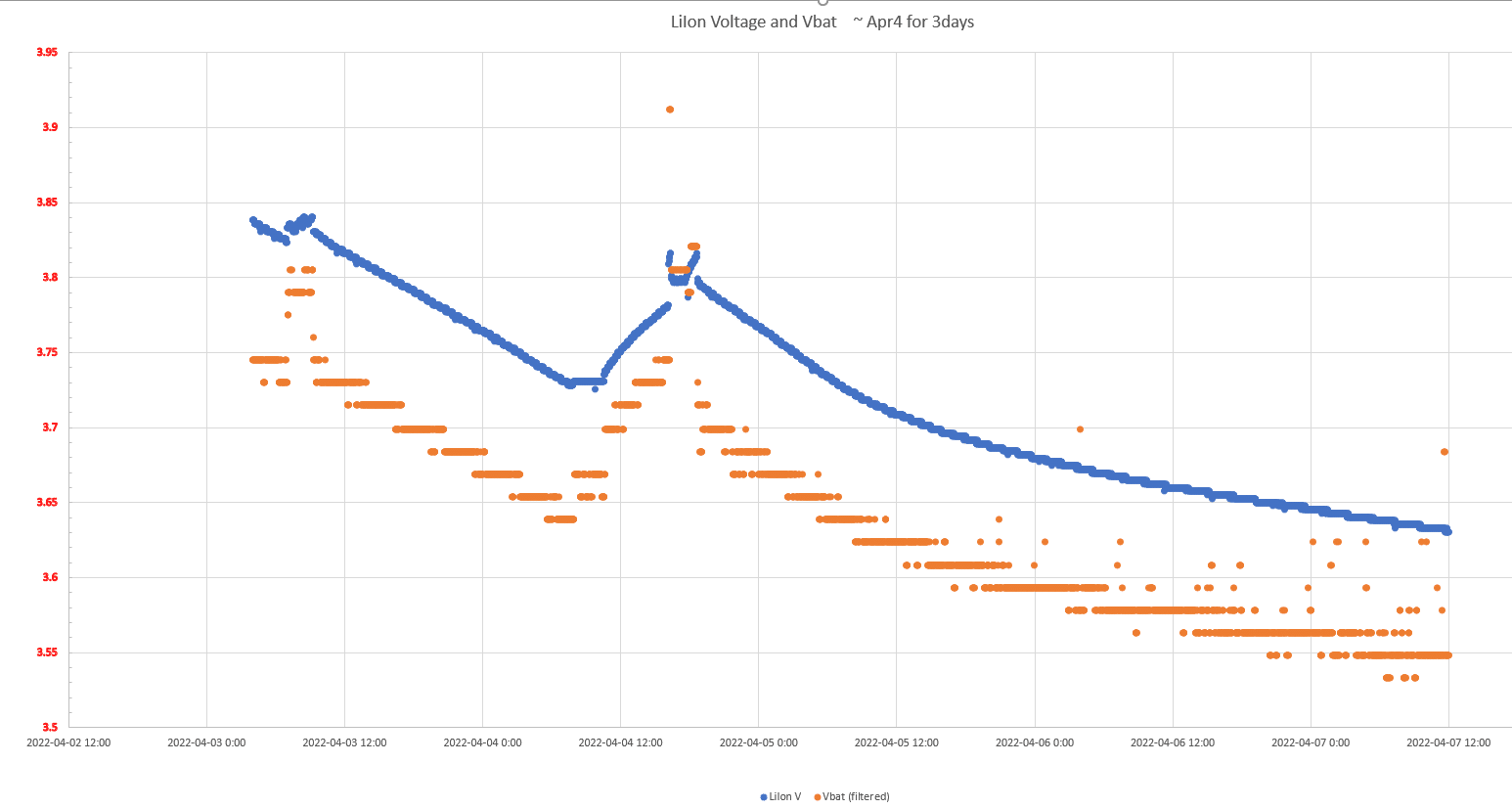
The two graphs are of the same period, one is from MMW that is a little easier to understand and annotated however has different scales for the Vbat/LiIonV. The second is from an xls graph, using the same scale, and has the quantization more visible.My conclusion is when using Vbat for determing energy available – use a filtered version of Vbat, and be conservative with the estimated low battery voltage.
I can submit my Vbat software filtering if it would be useful.
neilh10/ModularSensors/blob/release1/src/sensors/ProcessorStats.cpp #175 only for AVR.I use the Vbat threshold for determing when to cease reliable wireless transmission, and only store readings locally, ready for when battery energy is restored, and then bulk upload of readings.
neilh10/ModularSensors/blob/release1/src/BatteryManagement.h #192Of course your specific LiIon battery may be different, the Pkcell 4400 is designed for cycle life > 500 charge/discharges (not specified for a daily partial discharge/recharge). Once working, the depth of the battery discharge could indicate when the battery needs replacing.
@craig607 yes totally agree, spit balling or back of the envelope sketch
So great – you can see I’m asking the dumb questions, and if some one has to pick up the bottles every so-often, then can also switch out the power source batterys :).I see now how the hardware fits in, and found the schematics https://github.com/makerbase-mks/MKS-GEN/tree/master/hardware
Interesting, look forward to it@craig607 great to see the stepper functionality and managing it with the GCODEs though I wasn’t clear what the Marlin board is, and how it gets activated. Is the relay the power switch ON, or a pull to ground input.
This probably says how basic my view is, looking at powering, the 4.2V is nice as it maps to a LiPo battery, though LiPo are 4.2V decreasing to 3.8V. With 1.5As power draw the battery needs to be sized for the length of time the pumps can operate.
I’m imagining a use case of it being solar powered, so guessing at a separate LiIon battery pack, with probably separate charger and possibly solar panel – possibly all in the Marlin board? Just checking. Also, thinking typically need to measure the LiIon voltage to check its being charged.@craig607 fascinating, thankyou for the brainstorm.
Looking at the stepper motor power draw, seems like managing where that power draw comes from would be part of the design. For one source of steppers that give a range of V and A, there is a lot of choice https://www.adafruit.com/?q=stepper&sort=BestMatch
Happy to brainstorm that part if its useful.@lyh2o just thinking about this I wonder, assuming you have this in the office close to the computer that is programming it, if you could enable some debugging and post the trace here.
The debugging most useful is
-DMS_ENVIRODIYPUBLISHER_DEBUG
so depending on how you build, but if platformIO it would be on a separate line
build_flags =
-DSDI12_EXTERNAL_PCINT
-DNEOSWSERIAL_EXTERNAL_PCINT
-DMS_ENVIRODIYPUBLISHER_DEBUGThen after downloading it, to open a terminal and capture the output and wait for it to connect to the internet. Then it would be to post that capture here.
Fingers crossed -
AuthorPosts