@neilh20
15 days agoForum Replies Created
-
AuthorPosts
-
Great – I’ve asked https://www.instrumart.com/ if they plan on stocking it.
Something to note, a bit strange, is it comes up in SDI-12 mode, and needs an initial configuration to switch to RS485.
From getting some initial success – it may be worth starting with SDI-12 and getting some responses. Alternatively talk with a tech rep as to how they see this can be configured to RS485 before purchase.https://keller-druck.com/en/products/level-probes/multi-parameter-probes/series-36xiw-ctd
Then in the Manual https://download.keller-druck.com/api/download/yRqtkpbcVNQDHa3i7zdXDm/en/2020-04.pdf
As well as the standard RS485 interface, which provides access to
all configuration registers, the pressure level transmitter can also be
ordered with an SDI-12 interface. Only one interface will be active at
any one time. Corresponding commands are used to switch between
interfaces (default setting on delivery: SDI-12).From SDI12 manual ~ https://download.keller-druck.com/api/download/KMkeowTYmcRcUyZfadRVvZ/en/2015-11.pdf
7 Switch to RS485 (Kellerbus)
It is possible to switch from SDI-12 mode to the Kellerbus-mode (RS485 communication, Kellerbus or MODBUS RTU):
Description Command Response
Switch to RS485 (Kellerbus) aXC! aXC02Fe13! aXCD<CR><LF> (successful)
aXCE<CR><LF> (not successful)
After this command it is not possible to communicate over SDI-12 bus with the transmitter any more.
Be sure to have all hardware equipment for Kellerbus (RS485) available and the according software before switching SDI-12 off.
There is always only one communication interface active and the hardware of the other interface is switched of meanwhile and
can only be activated over a software command.A further note on developing a new interface over Modbus; is to then check that when its running the instrument is actually reporting well over that interface.
I’ve integrated an LT500 Modbus into ModularSensors – and the question now is how well does it perform. Does it actually report and work well. I’ve had this working well on the SDI-12, so I have good confidence it should
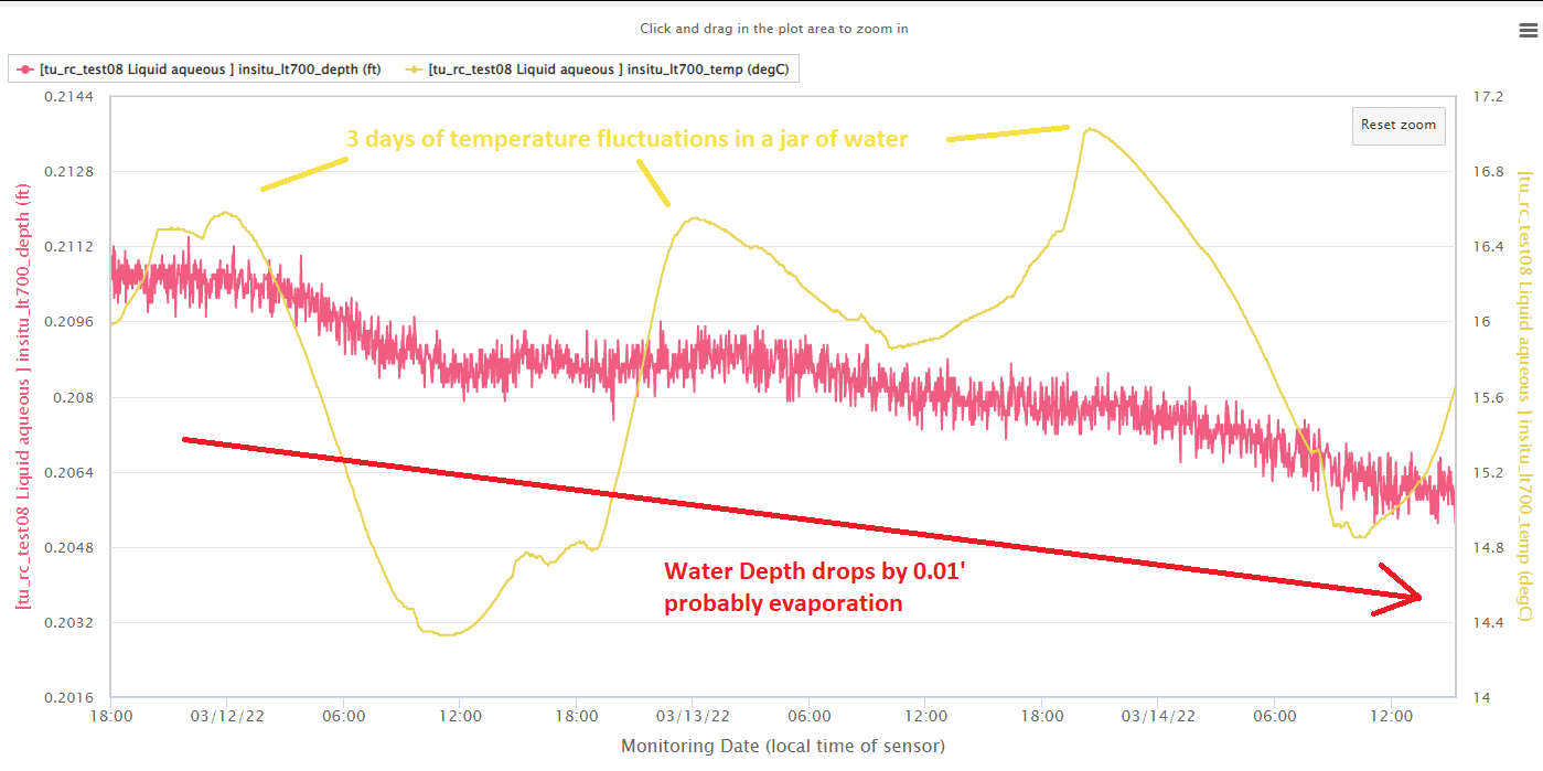
After running it over the weekend on a two minute reporting, with it sitting in a jar of water “0.21” feet deep – I have some confidence that the Modbus interface is working well. See attachment
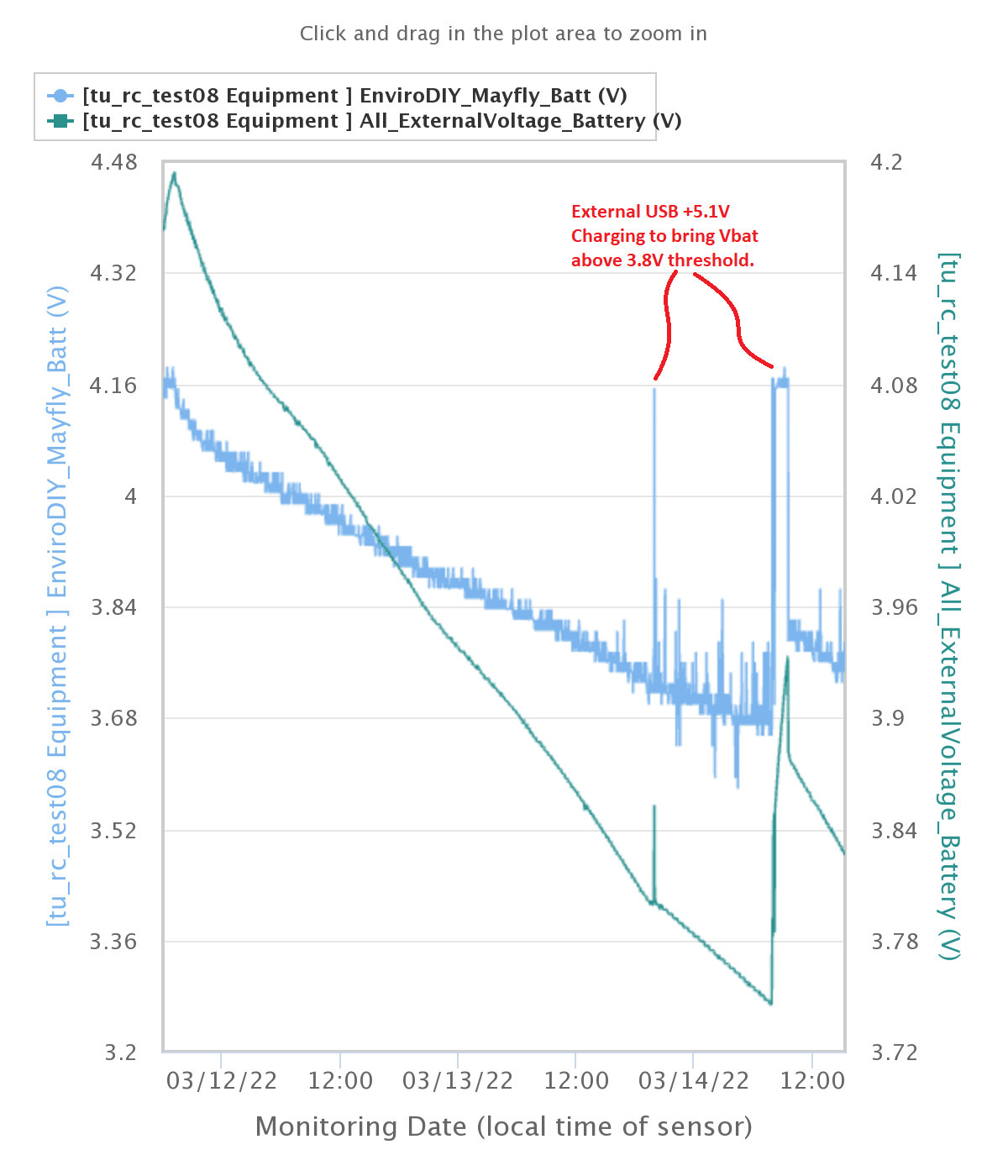
Its also running with the new Mayfly 1.1 and using the option to SJ27 to monitor the LiPo_V – which is a new feature of the Mayfly 1.1. So while it is doing the Modbus testing, I’m taking the opportunity to regression test the battery voltage measurement issues. This is testing the Vbat to measure the LiPo V to 3.8V threshold. The BLUE line is the 10bit Mayfly 1.1 measurement voltage. The GREEN is a reliable 12bit adc source. The BLUE Vbat is still somewhat noisy jumping around. I still have an open question as to whether it can be relied on.
@dan-wachusett I’ve just done quite a bit more work with modbus protocol, including developing an InsituModbus and though I would share here what I found out.
What its shown me is that possibly for the Keller CTD, a baby step may be to o start with https://github.com/EnviroDIY/KellerModbus and modify examples/GetValues to see if you can pull the values of CTD. If you can then, the next step would be to integrate ModularSensors class.
Erik any board that has a SAMD21 with a uSD/flashDrive and external RTC DS3231 https://www.adafruit.com/?q=DS3231&sort=BestMatch is probably a good target for using with ModularSensors. https://shop.sodaq.com/search/SAMD21/ and look for LTE cellular or other cell to match your local network. LoRa seems unlikely to work with MMW but could possibly with Arduino IoT
Also there are options at https://search.arduino.cc/search?tab=&q=SAMD21
The mega2560 and Mayfly mega1284 are 8bit versions, and excellent for low power, but short on ram, flash and peripherals
Hello Nancy, With some students we created a new site https://monitormywatershed.org/sites/SSU_ENG_SD02/ and its having an issue with displaying the time in the front page TSV and I entered an issue on it …
https://github.com/ODM2/ODM2DataSharingPortal/issues/560
Looking at your https://monitormywatershed.org/sites/Tom-Nat/ seems similar
and when I step to Vbat https://monitormywatershed.org/tsv/Tom-Nat/5286/ it seems like it did gets some updates to Vbat – latest Mar 3,14:10
So seems to be the same issue. You’re welcome also to add your findings as well if similar to https://github.com/ODM2/ODM2DataSharingPortal/issues/560
I’ve been building electronic circuits since high school. In case its of any use, I’m now using Kicad 6.0 https://www.kicad.org/blog/ and it has been excellent for reasonable human place able surface mount geometries of 0402 and larger. There is an evolving library of component footprints . Any non-standard footprint are possibly where the real challenge is with any circuit – matching the cu footprint to the component.
I have put up a basic Wingboard in Kicad as a starting point for a student project – https://github.com/neilh10/mayfly-esd-rev01
I prototype with oshpark and build my own boards as the first proto – oshpark has sophisticated help for Kicad and Eagle https://docs.oshpark.com/
The expensive and high risk part can be building a few test prototype boards to check the circuits. There are tutorials on youtube and sparkfun for prototyping – absolutely amazing. Start small and build bigger has been my moto.
I’ve built a set of RS485 wingboards with https://macrofab.com/demo/ – I liked it for the new online parts/BOM management and checking for parts availability in realtime. The output to Macrofab is https://github.com/EnviroDIY/Mayfly-Modbus-Wing/tree/master/knh002-MayflyWingShield/rev7
Of course a board assembled by a fabrication house is just the raw components “cooked” or soldered to make one board. It then needs testing to verify its working as expected.
As an EE I have been doing PCBs for over 15years with EasyPc (from numberone.com), and tried to pick up on Eagle 6 for some open source hardware, but the GUI was so specific that it didn’t really work for me. Just my experience, it does have a strong following so other people where more persistence than me have fun with it.
Well I’m working with some engineering students at 9am PST (10min) on how to modify Kicad files. A bit short notice but you could join in then if interested.
@Erik_G just an FYI, its made to look easy by Shannon, however it takes a lot of experience to get it right and then make it available as purchase.
Typically to do an order with a PCB assembly service, the qty of 50 is when there is the lowest cost per device. However assembly services only assemble to the instructions you provide. If you provide inadequate instructions, or they get it wrong. you still pay the full cost of assembly. Then there is also testing and configuration of the board, which is probably what you are hearing.
Unfortunately with the current world situation, I imagine its getting more difficult to export items from the US, as anything shipped out the country would require it to be certified as to where its going. However perhaps you can a packet of 5 or (multiples) from the enviroDIY shop, and do a swedish user group!
Just as refresh this is my data while working with a prototype SDI-12 level shifter.
@james_nz my process is to stage systems in an accessible context to check the reliability of the systems. This comes from the school of hard knocks working with embedded processors like the Mayfly.
IMHO while ModularSensors software has some fantastic classes to be able to access the instruments and also to push to cloud locations, Arduino Open Source is generally at the level of – Arduino teaching ~ this is how it can be done.
Its next to impossible to teach “reliability” – its usually learnt through being on the “bleeding edge”. The 2nd time around one tends to add more foundational capability to better cope with reliability testing.
You reference “dropping out” which can be a whole record or one instrument. A record lost is typically due to “internet failure”, but still stored on the uSD.
Individual readings, usually digital instrument, when the digital comms link to the digital instrument fails.
It seems, for the above referenced node, your RS485 instruments are responding OK, its the SDI-12 instruments that are having comms failures.
Its should be noted that the Mayfly’s xx could be said to support “Arduino SDI-12”, that is they show how it can be done, but there is a lot of technical debt. It isn’t per the SDI-12.org specification for signaling and protection.
I’ve been trying to prototype a solution to this for some time. Right now my RS485board includes SDI-12 protection and level shift. However I still need to work on the SDI-12 software for it to cope with the level shift. https://www.envirodiy.org/topic/sdi-12-level-shifting/
Currently when you access the Mayfly X with the USB cable (or even the FTDI cable), it causes the Mayfly to reset – a nice Arduino feature of always making sure the board can be programmed. However that reset isn’t good for reliability monitoring – that is plugging in and just monitoring how its been working – I’ve created a modified FTDI connector to allow that https://github.com/neilh10/ModularSensors/wiki/Test-Equipment-FTDI-cable
-
AuthorPosts