@neilh20
8 days agoForum Replies Created
-
AuthorPosts
-
@James_NZ – are all your setups the same?.
Have you got a spare setup that can be debugged in a local setting? (office with terminal connected)
I have a similar setup with an RS485 and SDI-12 on one system – but I maintain a test system to verify it before I deploy it.
https://monitormywatershed.org/sites/TUCA-Na13/
I have done work to ruggedize it. All I can do is describe how I do it.
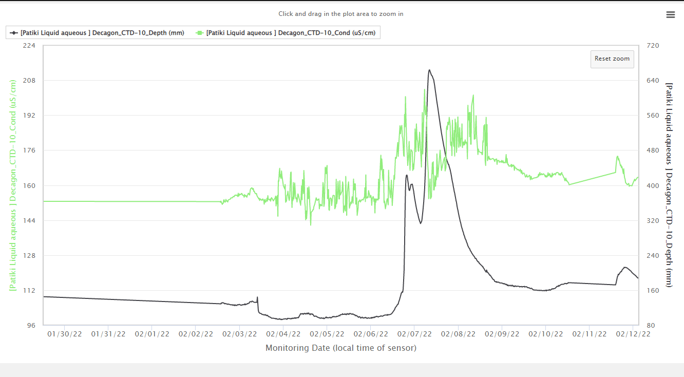
@James ouch. Looking at the data file, its just the Decagon CTD/SDI-12? readings that are responding -9999 . Typically that means the (SDI-12?) protocol has failed to communicate with the instrument.
At the same time Yosemite/Modbus? is responding well.
The CTD is only occasionally failing, or failing in groups, but still working some of the time. A hard failure where it fails all the time is easiest to debug. Intermittent failures are the hardest.
You started running the setup 2021-10-25 11:16 and
then it started failing 2021-12-09 14:45
and recovered 2021-12-14 13:00
Did you do anything to have it recover?
Since then it has intermittent failures. Ouch that is the hardest to troubleshoot.
I have one LT500 that is not working well with SDI-12, its mostly failing, but sometimes works. Similarly I purchased a device that is tested to the full SDI-12 device, and its also failing a lot. SDI-12 from the Mayfly is not a standard 0-5V, so I’m planning on moving it to the Modbus. I’m also trying to figure out a way of generating a fully specified SDI-12 0-5V
Attachments:
Nuts you lost one.
Unfortunately it take the Digi “Xbee TH Development Board” to do an upgrade. Hopefully the new ones will be come with the latest software.
Hi Dan, wow interesting it works to 3.2V. Yes RS485 should work well and it can go a long distance.
You do need a physical RS485 driver wing board that will fit with the UART pins. RS485 is a specific differential voltage protocol that can travel thousands of feet on two wires. The instrument requires 4 wires. See above for examples.
My observation is that enviroDIY is about a safer space to try things out, but you still have to figure out the process that works for you, and as ever the budget that can make it work.
EnviroDIY can be the place to share insights like I’m doing and Anthony is doing. As its your instrument you are the lead person, others with deeper knowledge of say the protocols can lend some insight, but implicitly you own the making it work.
Gosh it seems like you have your feet very wet already with the Mayfly. My experience is to plan the development process and manage the expectations of others of the risk. This is what we teach Engineering students.
This can be low budget, but only if you have the time and commitment to learn the Modbus protocol. Keller does publish where the extra 36XiW-CTD registers are in the Modbus map. Modbus is archaic but because it runs on RS485 it works over a long distance. For trying it out you only need one 36XiW-CTD and your commitment. For serious development we typically plan how to reduce the risk. The first part is to test that the protocol can be interfaced to. Then how to do the full integration test. That is one 36XiW-CTD for the lab bench to check the protocol with quick turns of the software. Then one for a realistic practice area otherwise known as stability testing, and one for the final stream. In the long run maybe the tests ones can be deployed to streams, but every time there is a new software release its better to have a safe place to check the new software. In the open source world, other people may offer to lend their experience, then typically you pay for their instruments.
Hope that helps.

Thanks for checking with Dave on that. Good points about what might create some sounds.
Hi Dan
Very interesting – I like that conductivity measurement port up from the depth measurement port – out of the mud so to speak. It looks to be at least 30mm up the sensor column. And that’s a difficult mechanical feat. I wonder where you have a quote from. I’ve got Keller sensors from https://www.instrumart.com/brands/1051/keller – but they aren’t showing this model.
I would say the short answer is RS485 and a working +12V (IHMO boosted from 4.0V) ~ as Shannon was saying . Partly it depends on the distance from the measurement place to the Mayfly Enclosure. 36XiW-CTD RS485 protocol identifies 1,400m, which can go through intermediate wiring connection points. Mayfly SDI-12 is unspecified
I’ve implemented the Keller RS485 protocol ~ See KellerXxxLevel.h on https://github.com/EnviroDIY/ModularSensors/tree/master/src/sensors and used it with a +12v boosted from +4V.
I’d be interested in helping, and would need one of the instruments, but in the end its new development for ModularSensors and would have some risk until the first message had been successfully polled for.
I found the data sheet at https://keller-druck.com/en/products/level-probes/multi-parameter-probes/series-36xiw-ctd
Practically Mayfly 1.0A3 doesn’t have a working +12V, and hopefully the new version of Mayfly 1.x will have a power specification to the +12V so it can be matched to what the Instrument requires. https://github.com/EnviroDIY/EnviroDIY_Mayfly_Logger/issues/33
Hopefully Shannon’s RS485 will have some visibility soon – https://www.envirodiy.org/topic/rs485-schematic/ and if it all works, its a very nice combination.
However there are two other RS485’s board with boost to +12V, one of which I’ve implemented https://github.com/EnviroDIY/Mayfly-Modbus-Wing/tree/master/knh002-MayflyWingShield
A perspective, from working with Insitu LT500, the SDI-12 implemented on the Mayfly is a subset of the SDI-12 Specification. https://sdi-12.org/ . That’s technical speak for saying you’ll have to try it to see if it works, for an instrument range and for each instrument thereafter.
As Shannon said a level shifter is needed – from out-of-spec 3.3V to specified 5V – and there has been a lot of discussion about the “Half-duplex” level shifter elsewhere, which with the SDI-12 software is complex to get right.
The Mayfly software implementation for SDI-12 protocol doesn’t include the CRC option, and the RS485 version has that implicitly built into. I’ve been looking at this, https://github.com/neilh10/ModularSensors/issues/68 and got a version of hardware to test it against https://vegetronix.com/Products/SDI-12-Sensor-Translator/ (its lower cost than an LT500 for regular testing.)
The Mayfly SDI12 subset is not protected from voltage (lightening, ESD) as per the recommendation in the spec.
As ever, hope this isn’t too much info, The 36XiW-CTD looks very interesting . I’m happy to chat on 707.780.1569 .
Also I’ve listed it at https://github.com/neilh10/ModularSensors/issues/100
@zeke-holloman communications – peer2peer – is a deep subject.
Many years ago I wrote the code for a comms stack to use the 9bit UART to poll an array of processors. In the end it was 2people for 18months to get it working reliably. So its not trivial, but i had a fantastic time with it.
https://forum.arduino.cc/t/uart-with-9-bits/612497/19
It may that you have a special case and only want to use 8bit communications, it partly depends on what you want to communicate.
Hey great. Many thanks
@shicks just wondering if the RS485 schematic is likely to be published, and of course if the parts are likely to be available. Many thanks.
Ok. Got it running with a student I’m working with (over zoom)
1python -m serial.tools.list_ports -vshows the ports and then substitute for “FTDI”
So in https://github.com/EnviroDIY/Sodaq_DS3231/blob/master/examples/PCsync/python3.9/PCsync3.py
about line 101 subsitute
“Silicon Labs”
(or maybe there is an OR function – but I don’t recognize the iterator )
-
AuthorPosts