
@neilh20
5 days agoForum Replies Created
-
AuthorPosts
-
@tumayflybearriver – thanks for brining it up. Its nuts, but looks to me like the signature of “thrown away data” by ModularSensors software that runs on the Mayfly, and the ODM2 software on monitormywatershed.
I’ve raised the issue of reliable delivery in 2018, and implemented it on my systems and offered it to the mainline ModularSensors
The story https://github.com/EnviroDIY/ModularSensors/issues/194
https://github.com/ODM2/ODM2DataSharingPortal/issues/485
At the request of some SWRC parties last year I submitted it to ModularSensors main software, but other priorities came up and it seems it was abandoned when it was nearly integrated into the mainstream.
Otherwise, to verify for your specific node, Shannon is right. Its looking at what is stored on the csv file and is that data on line. Might be just easier to use the .csv periodically. If its on the .csv and not MMW – then it was collected and “thrown away” by the software.
I’ve done it with my tests systems that where local to me – and it was a lot of work to get my forked version of ModularSensors reliable. I’m very happy with the data that my systems as part of TU N california are collecting.
The story for my TU systems in N California .. https://www.envirodiy.org/n-ca-mayflys-through-the-winter-storms/
Its great that ModularSensors is open source, and I’m very happy with my fork which anybody else can use as well .. https://github.com/neilh10/ModularSensors/wiki
happy to chat about what I think it takes to improve system reliability if interested, but you can also look at my blogs on it over the years

Hey thanks for the reference. I’ve also been monitoring blynk .
Do you offload the data regularly? – that seems to be the big gotcha is figuring out how often to download data.
Hi @braedon-dority, my take is that the first step is to have personal documentation to be able to repeat your work, and that you can read it. Just to be basic, part of the learning is how to do documentation that you can then read your self.
Personally I find I come back to a working sensor some years later – and then want a traceable reference to what it exactly is it, and how do I a) repeat it b) modify it. For instance I still have a sensor working that records my tipping rain gauge – totalizer raindrop counts – and posts to Thingspeak – but was using a platform I stopped using. So I want to know what it does, but if I think of repeating it, I’m likely to try and do it differently.
So yes I find a very specific wiring list, often on a spreadsheet, but can be a document. A picture is good as its often worth a thousand words. For me the hardest part is often slowing down enough, to review the documentation and see what might be obvious that I am leaving out.
The fritzing I take to be away of presenting to other people to help them understand. That is so much more work to do, to become an “influencer” or teacher.
Anyway just my take
Congrats – nice to see.
I guess the fundamental problem of power management is still there and can bite any time the power drops – and then likely will require a site visit to get the site restarted. Getting enough power is a band aid to enable reporting readings. So long as the power supplied exceeds the power used by a good margin it works.
I’ve found the real fix is in software using higher voltage thresholds – but it causes tradeoffIts interesting the shape of the 2nd charging pulse – indicates lost data. Stepping to the larger graph, its more visible.
So the next layer of reliability issues, with the fix being in software. I predicted the problem in 2018, and had a solution for it in 2020 that I’m using,
Orderly data delivery – Queue messages for later sending,
So just advertising there is a fix for it
Attachments:
@jamesp thanks for sharing. Interesting where the “banana skins” are to slip on.
Nice to know its got low quiescent current – end of last year I also got the same SanDisk Industrial MLC MicroSD SDHC UHS-I Class 10 SDSDQAF3-008G-I withs its specified Operating Temp Range: -25°C to 85°C , but haven’t measured its current
I’ve bought uSD with “white” so I can write on it to track individual cards.
I was using SanDisk Ultra SDSQUNS-016G-GN3MN 16GB (10 Pack) for most of my systems – however it hasn’t got an outdoor temperature specification. I had a problem with some occasional resets on one of my systems, so I switched it to the above.
@jamesp I wonder how the systems are faring?
A follow up – I had this running for about 6 weeks last year.
The code is in my fork is at https://github.com/neilh10/ModularSensors/tree/release1/examples/samd_log_display_mmw and is available to the main at any time.
For test purposes, I positioned the temperature sensors in my office, attached to different areas round the heating vent, with the winter heating kicking in.
This is is very much an alpha test – its designed to do an end-2-end system test and characterize areas that need more work.
What showed up was the difficulty in labeling or easily “tracking” what was being measured . It turns out there isn’t the capability to give multiple sensors of the same type (DS18 thermistor) a “nickname” to describe the location that they are positioned in
I documented it here https://github.com/ODM2/ODM2DataSharingPortal/issues/686
For the DS18 temperature sensor readings to be easier to decode and track – the Arduino world of make it easy – I would want to add distinguishing labels – hints to understand the graphs – “Vent Output”, “Vent Underneath”, “Vent-Horiz 1ft”, “Window ledge”
Of course for analysis it can be repeatedly downloaded – brought into a spreadsheet, and meaningful labels added/
Some other issues,
I wanted to configure the DS18 temperature sensor s/n in my .ini file – to make it easier to manage the sensors. However for some reason moving the DS18 from standard static initialization, to a dynamic initialization and then setting the s/n number failed to work. It should be easy – but that’s the story with software – I’m missing something somewhere. In the interests of trying out the alpha test config I created a bug to be able to track it later and moved on
As I had discovered in testing, the Wio Terminal internal WiFi networking module RTL8720 – has some problems with hanging when dealing with external conditions. A couple of other people have the same issue, No answer from Wio Terminal about this. https://forum.seeedstudio.com/t/rpcwifi-problem-when-wifi-is-lost/262273/4
As expected from a circuit analysis the Wio Terminal, while nice looking, doesn’t do Low Power. I had wound down the clock frequency to use as little power as possible, and still the 6Ahr battery lasted about 2.5days.
Conclusion : This has shown that the ModularSensors modifications for SAMD51/SAME51 processors with ARM tools works. The SAMD51/SAME51 is good fit for a sensor node as it has an architecture with number of configurable serial peripherals – including possibly up to 6 serial UARTs+I2C+SPI, and 32DMA and 2MBytes program flash + low cost external flash that can be dual usage. However I need to try with some other SAMD51 boards that can achieve a low power state. I have a few Adafruit options, some with LCDs. I also need to be able to easily interface to an LTE Modem, and for Modbus generate +12V & RS485.
Other processors include the newish lowish power, ESP32-C6 with 3 UARTS could also be attractive, but is a different tool set. The ESP32 based “M5 Stack” boards are trying for lowpower by turning off the electronics all together.
2023-12-20 at 8:36 PM in reply to: Changes coming January 1, 2024 for Monitor My Watershed users #18264I’m very much a fan of ModularSensors and the discussion board as a place to be real with technical issues. I do so appreciate the unique place EnviroDIY has been curated to be, to try some remote wireless terrestrial monitoring. Its the nitty gritty of environmental monitoring and the engineering it takes. Its tough to find out what these services cost – so hope it works out. I’ve contacted the funder of the project I’ve been in to let them know of the late changing conditions. On a commercial scale the initial entry is pretty low cost , but going to be expensive if it scales. I hope it can keep up with the demanding changing technical bar.
There are some really nice features mentioned, though I’m curious as to whether this constitutes a “Service Level Agreement”, and is there a verification plan.
A critical technical statement that is missing is the expected response from the server. Device POSTing is only as good as the servers response time.
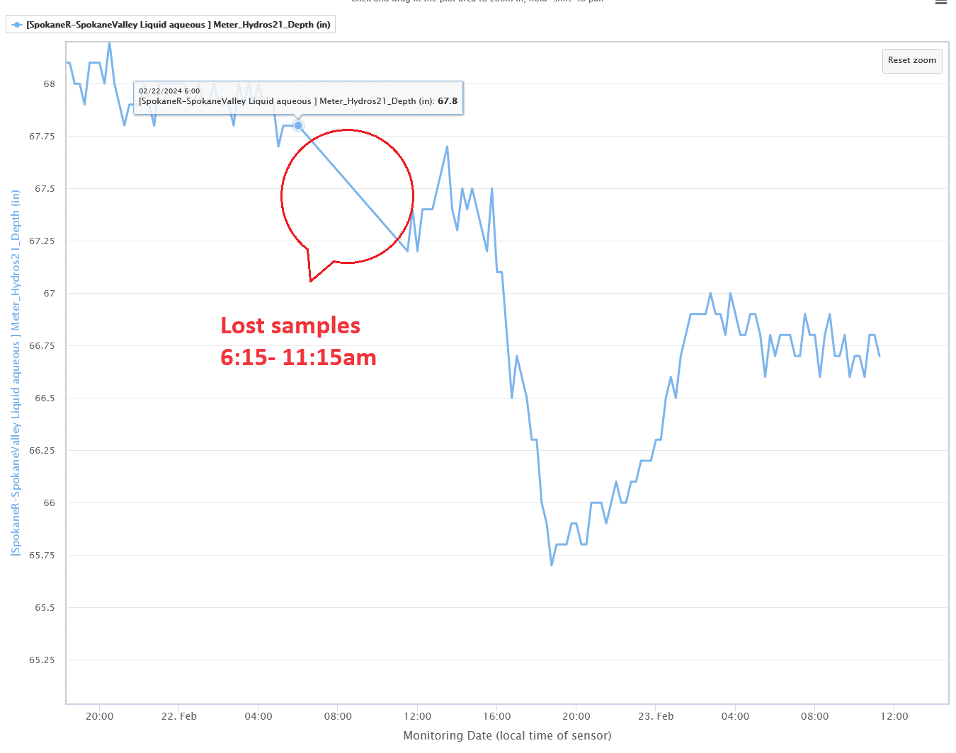
There have been a couple of windowed losses in data storage on MMW and the subject doesn’t seem to be addressed-
https://github.com/ODM2/ODM2DataSharingPortal/issues/605
https://github.com/ODM2/ODM2DataSharingPortal/issues/685
and I brought it up locally – https://www.envirodiy.org/topic/mmw-lost-readings/
so curious how real-world issues are going to be addressed. Many thanks. Neil
I haven’t had much luck getting to 0.5mA with mega1284, it was with the Mayfly 0.5b- https://www.envirodiy.org/topic/testing-power-consumption/#post-15252 My notes on measurements is that it was between 2-2.5mA. I did get well beneath 0.5mA on another project with mega2560, but that was a lot of hardwork, and also ended up with a higher value of mA for the production version – as the modem connection really consumes the energy.
In looking at testing the whole system, including production software – I came to the view its the apparent reliability of the overall system – and managing the power demand, and delivering readings to MMW, that results in a stable overall system – requiring less intervention and maintenance.
I put a model together for power used over a day with the most active subsystems. I enclose “Mayfly MS Energy Useage 231218.xlsx”
This is really paying off with this system https://monitormywatershed.org/sites/TUCA_GV01/
Attachments:
@jp – the charger relationship doesn’t quite work that way. The 5V 2.0A is typically the stated maximum the charger can supply – however for the battery charger circuit there are limitations. I use a USB Meter to determine what is actually going on.
The Mayfly 1.x charger circuit is to 0.5A as default but can be changed to 1.0A. I always change my boards to 1.0A See ” SJ15″ https://www.envirodiy.org/mayfly/hardware/jumper-settings/
The yellow “Charge” LED at location “S” only comes on when it is charging the battery – so a sign of it charging is that it comes on when plugging in, and then when completed it goes off. These are different than the LEDs at USB-C location “C” labeled “power” and “USB”
The LiIon charger does manage the battery and has effective feedback
For LiIon power storage calculations its estimating Power-Out over perhaps two weeks, the length of no solar say in a storm – its a soft figure but that’s my estimate. Then when solar returns – the power-solar that is going to recharge the battery – in says two days of solar in winter with a cold battery.
From what I saw your solar panel was providing a charge earlier in the year, but now with winter conditions is not.
Power-Out is also dependent on many factors, the largest power user is usually the modem – and this can vary by time of year – I find it takes 26secs to connect to the tower, and then it takes time to establish a TCP/IP link to the MonitorMyWatershed – and then POST the readings, and sometimes even longer for a timeout. If the physical location is on the edge of the cell, then connection conditions can really way out. In addition if the Li-Ion battery is at a low charge state, and also cold, it sometimes can’t supply all the power needed to connect the signal and effectively reset the process. The Li-Ion battery power availability might be on the edge temperature wise, work in the afternoon when it has warmed and then fail when its colder.
For battery voltages – my measurements on the Vbat indicate its non-linear. Its not very accurate particularly in the range that is really needed 3.4V-3.8V – I’ve calculated that the error in reading using Vbat is +/-0.2V .
I use a 3.8V threshold to gate using the modem. That is when the Vbat measures 3.8V – the battery could be somewhere 3.6 or 4.0V and I don’t invoke the modem. I use a value of 3.6V to stop doing any processing.
The SpokaneRiver-Peaceful.ino and SpokaneR-SpokaneValley.ino both use a 3.55V to gate the modem – which are defined in ModularSensors\examples\DRWI_SIM7080LTE\DRWI_SIM7080LTE.ino
However one systems battery goes low – and it resets on power demand, and the other systems battery stays above 4.0V
The way I read ModularSensors\examples\DRWI_SIM7080LTE\DRWI_SIM7080LTE.ino is its an “example” – there is no testing of edge conditions that I have seen of that actually test and verify that a SIM7080 modem can work at 3.55V in cold weather.
I have actively monitored and tested 4.4Ahr battery and documented it here https://github.com/EnviroDIY/EnviroDIY_Mayfly_Logger/issues/32#issuecomment-959807618 .
Due to high value resistor ratio its also a noisey signal – and I document it here – https://github.com/EnviroDIY/EnviroDIY_Mayfly_Logger/issues/36
IMHO the measurement technique of reading the physical ADC twice in succession and using those values separately isn’t good for this type of high impedance noisey ADC measurement. I use an algorithm to read the ADC a number of and then take the lowest reading for those Vbat readings, and then use it in both decision loops.
Power availability is complicated when its on the edge. As far as I can see the Mayfly 1.x Vbat has never had its accuracy defined. Accuracy is related to both resistor variations, resistor noise and ADC Vref accuracy. Mayfly 1.x Vref is a vast improvement on the Mayfly 0.5b hardware realization.
So this is what I would think is a good starting point
1234567891011121314151617//Get realistic battery voltagefloat vBatLow = getLowestBatteryVoltage();#define VBAT_WORKING_THRESHOLD 3.6#define VBAT_MODEM_THRESHOLD 3.8// At very low battery, just go back to sleepif (vBatLow < BAT_WORKING_THRESHOLD) {dataLogger.systemSleep();}// At moderate voltage, log data but don't send it over the modemelse if (vBatLow < VBAT_MODEM_THRESHOLD) {dataLogger.logData();}// If the battery is good, send the data to the worldelse {dataLogger.logDataAndPublish();}The simplest solution for the current systems is provide enough power to keep the LiIon battery charged up, with a bigger solar panel. If at this time of year if it starts to drop below a measured 3.9V go out and plug in a USB Charge bank to boost the battery.
Alternatively if easy also modify the Mayfly 1.x for SJ15 so that it takes more charge when available.
Once there is more solar it probably will maintain more power in the battery.
-
AuthorPosts