@neilh20
5 days agoForum Replies Created
-
AuthorPosts
-
Do note that the specifications says accuracy 0.5% of 10,000m or +/-50mm (edit corrected to 50mm). This implies that you want to keep it at a constant (20C?) while sitting in the bucket, and even then the apparent water level can wander up +50mm or down -50mm and still be within specification. If the temperature changes then the accuracy specification doesn’t apply.
https://www.metergroup.com/environment/products/hydros-21-water-level-monitoring/
Water depth
Range: 0−10,000 mm
Resolution: 1 mm
Accuracy: ±0.5% of full scale at 20 °CNOTE: Depth measurement accuracy assumes no abrupt temperature variations.
For environmentally significant flows (low water depth measurement, with high temperature variation) it has a lot of noise on the signal.
Great instrument for measuring borehole water pumping ground water that is usually a constant temperature and large variation in depth.
Sometimes there is no easy answers. I recently went to presentation that included this analysis for
https://creeklands.org/wp-content/uploads/2021/02/CLC-Micro-Flows-2020.pdf
So partly what range of flow are you looking for and what accuracy.
Hello James, yes I have a few hybrids that are working, that’s the way that they have been working up to now. I would think you’d want to test your 10 ASAP. For me the devices that did not work, they just they didn’t work. So for testing its they either work or not. As an electrical engineer I did do an analysis and laid out what I had done, but it didn’t really make a difference.
This is a custom build, to a specified qty, which I will place on Tuesday. I had thought of a kick starter framework, but that was going to take more time. There is NO excess to sell on a market later, as that gets so complicated.

Manufactures want to be paid up front for what they build.
I got all the parts and the PCB yesterday, so building the proto tomorrow to verify the parts. All the details will be available as an open source hardware build, so it can be build later, either yourself or choosing a supplier of your choice. I’m sure they have small manufacturing shops in NZ. Also the hardware can be easily modified if required.
https://github.com/EnviroDIY/SensorModbusMaster/issues/14
In a nutshell, the low cost RS484 hybrid often doesn’t work. Technically the QA of the workmanship is untracked.
My test06 system froze for a 2nd time. This time I pressed the User Button, which is also tied to an interrupt, and started up again. I have made updates described here; https://github.com/neilh10/ModularSensors/issues/34 and restarting the testing.
Ok thanks.
An update to my stability testing, this partly makes me collect the dates and status.
A test system “tu_rc_EC” standalone EC “Stream Disconnect” monitor built on 0.25.0 has been running since the beginning of Oct very well. I plan on describing this and haven’t done so yet.
The “TUCA-NA13” remote Verizon wireless system in the wilds measuring a stream depth, with two gauges – Keller and LTC500 – built on 0.25.0, has stopped recording on MMW on March 28. It started on Jan 29<sup>th</sup> after a previous outage, so ran for 2months. It is very remote and appears to go through periods when the Verizon network has low signal or MMW is not responding, but it has always recovered. A site visit next week might restore it.
An early beta “tu_rc_test06” is in my yard, and a duplicate of the TUCA-NA13, with version0.28.3. This is from my fork, with extra features, but based on 0.28.3. It stopped running, and I have a terminal on it that caught what happened
So tu_rc_test06 started Apr 1st (it survived Apr 1st), and froze on Apr 19<sup>th</sup> . Looking at the log, the Mayfly awoke at
… zzzZZ Awake @ 2021-04-19T16:07:00-08:00
then POSTED to MMW successfully
— Response Code — 201 waited 2107 mS Timeout 5000
Going to sleep. Ram( 6127 ) ZZzzz…
Watchdog disabled. barksUntilReset 150 <–WatchDogAVRthen never woke up.
At a guess, a hypothesis, the RTC clock never woke it up.
@srgdamiano I wonder if you’ve seen anything like this?Looking at the Sodaq_DS3231 RTC it reinitializes every sleep cycle. In another life, working on a large product, we had some very occasional reliability issues with the I2C bus. When there was an issue it was spectacular, and once happened before a very visible customer. We came up with a workaround.
The I2C hardware protocol is not a guaranteed transaction, and could have noise on the line. So I’m trying a modification that does a read of the Sodaq_DS3231 registers to verify that they have been set correctly. It is a long shot, and happy to take any suggestions.
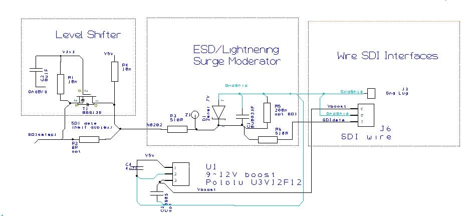
Hello @shicks ~ I’m just following up on this as I’m respinning my Modbus Board MayflyWingShield schematic.pdf
to have a SDI-12 interface, and your board got me thinking .
The Mayfly socket has +5V and +3.3V and the board can have the boosted +12V. ( I had done it from the Seeed D6-7).
So thinking of trading off the third 4pin “modbus socket” for a 3pin “SDI-12 socket”. That is 3pins screw connector and “JST PH 3-pin”. The JST PH 3pin 2mm have Adafruit mating cables.
The line interface following https://sdi-12.org/specification
The benefits are one digital interface board, with options for simplicity like 3.3V pass through interface, or plain SDI-12 instrument +5V current limiting.
So just putting it out there for a technical review if you have insights/comments ~ always appreciated before committing to copper.

Attachments:
Hello @shicks thanks for the response. I was thinking partly of the SDI-12 specification modules driving 5V back into the 3.3V ports. The Insitu LT500 that I’ve been using does respond to Mayfly driving it on 3.3V, but then drives back SDI12 specified 5V which has to be mitigated.
Do you see any issues with the level shifter and the port interfacing software interface on the Mayfly. https://github.com/EnviroDIY/Arduino-SDI-12
I guess I’ve been trying the option above, and again the LT500 seems to then not respond. A slight difference is that when Mayfly port is in tri-state, which can looks like 0V, the level shifter pulls up which then looks like a 5V. So the level shifter flips it.
Seems like that shouldn’t be a big issue – but then the LT500 didn’t respond, so became a headscratcher.
So very interested to continue the conversation and I’m happy to proto type a trial circuit.
I’ve been working on a next revision board. Details at https://github.com/neilh10/SensorModbusMaster/tree/release1/hardware/knh002-MayflyWingShield
overview at https://github.com/neilh10/SensorModbusMaster/tree/release1/hardware
I don’t have any time frame on availability due to the world wide shortage of parts, but probably third quarter this year. It will be an order before hand build so good timing if you are thinking of getting some.
I have hand built some for testing, and now have them testing on a system with a Keller Acculevel /0.28.3
I’ve got it on my list to do more write up.
-
AuthorPosts