@neilh20
16 days agoForum Replies Created
-
AuthorPosts
-
Sorry Matt for the lingo – its hardware speak.
 It was on at least two Mayfly 0.5b that I measured.!! I now measure the LiIon via the ADS1115 – here is what the two measurements look like in the field. A lot of work to get it there. They have the 4400mAh battery from Adafruit, and 3W solar panel.
https://monitormywatershed.org/sites/TUCA-Na13/

Fancy that Turner Turbidity Plus sensor!. Interesting spec, says its supply is 3V-15V, but not clear what the wiper takes at 3V. It specifies the wiper at 12V@280mW (23mA?)If you haven’t got an easy interface to the wires from the Mayfly, the “RS485 boards” could provide a reasonable interface to the wires (you wouldn’t need the separate RS485 hybrid)
https://github.com/EnviroDIY/SensorModbusMaster/tree/master/hardware/Modbus-Mayfly_WingShield
If it needs the 12V for the wiper there is a range of Pololu boosters that fit on the board 12V. U3V12F12
If you want to switch directly from the LiIon bat, I have done this new board
Also I’ve put on an STC3100 Battery monitor that can measure V and mAHrs/Coloumb counter – looking interesting so far though, still a wip https://github.com/neilh10/STC3100arduino
Attachments:
Just a note, I’ve switched to an STC3100 “Battery monitor IC with Coulomb counter“. The LTC2942 became unavailable and turned out to be more expensive.
I’ve got the basic driver here – the device driver reading the registers is here —https://github.com/neilh10/STC3100arduino
A device manager that can provide power consumed in mAhrs is still wip.
I’m using it with an enhanced RS485 power board that supplies power directly to the 4V to 12V booster – and it can supply a continuous 1.9W.
This a new board, and if anybody wants one they should let me know this week so can be included in a manufacturing build.
A status for testing with 0.28.01 – after integrating to this release with the SDI-12 bug fixed and then leaving it running for two weeks, using a Verizon LTE CAT-M1 has worked very well. A deliberate characteristic of this test setup was to have a very limited solar aspect a small charge at maximum 0.5A in the morning- but the overall power usage has been pretty low. U
Any usage of the Digi WiFi/0.28.01 soon gets hungup, and I plan to look at it.
On my fork I also have a BatteryManagementSubsystem combined with a reliable delivery that have worked in combination very well.
The following picture summarizes my testing.

Jim fascinating, thanks for sharing and been re-reading your document a couple of times.
(I’m redoing my previous post as I got a bit excited with a power discussion).
I use a higher threshold V for transmitting cellular information. The voltage is dependent on the battery type/capacity and the load on the battery.
I use 3.8V as a threshold to stop transmitting,.Under 3.8V I’m reserving the power to purely take readings, and extend the length of time that readings can be taken. Objective is at least two weeks.
On a transmission attempt, if the Voltage is above 3.8V then it transmits all the outstanding readings taken under 3.8V.See this test that shows this.
So a question, from your document, how are you measuring the LiIon battery voltage?
I don’t have good results from using the Mayfly’s mega1284 Vbat.
I put some data out and never got a response https://www.envirodiy.org/topic/battery-measurement-accuracy/
I implemented a separate monitor on ADS115 AA0 https://github.com/neilh10/ModularSensors/wiki/Hw-Mayfly-ECO-R04
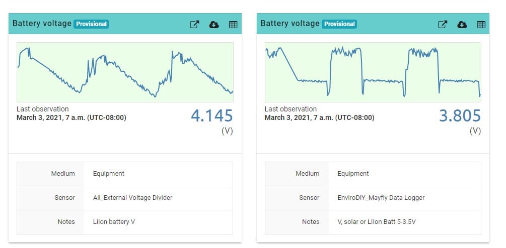
The results can be seen on the two Battery Voltage measurements on https://monitormywatershed.org/sites/TUCA-Na13/
For maintenance the “EnviroDIY_Mayfly Data Logger”/”V, solar or LiIon Batt 5-3.5V” indicates there is a good solar aspect charging the Adafruit 4Ahr battery.
The AA0 sensor “All_External Voltage Divider”/”LiIon battery V” indicates how well that solar aspect is charging the battery.

Attachments:
Through Digikey RevX there are some new data plans that cover up to 50MB for $6/month
https://dataplans.digikey.com/
Using Digi LTE CAT-M1 modems, with Verizon SIMS from Digikey, transmitting 8 values, taking readings every 15minutes, and attempting reliable transmission every 2hours, in a riparian valley in a remote area of N California, (so retransmission when the wind blowing wrong direction or fog) I’m seeing about 2.5Mbytes a month. Well within the 50MB.
CAT M1 – 50MB STARTING AT $6 PER MONTH (US & NORTH AMERICA)
► AT&T CAT-M1 50MB @ $6 ( $0.40/MB OVER ) – US / CA / MX – (no lines present)
► VERIZON CAT-M1 50MB @ $6 ( $0.40/MB OVER ) – USA – 1 LINE(s)https://monitormywatershed.org/sites/TUCA-Na13/
I guess should check LTEIn case its of interest, I’m using the EEPROMClass from EEPROM.h
\.platformio\packages\framework-arduino-avr\libraries\EEPROM\src
EEPROM.put(EP_PERSISTENT_STORE_ADDR, epc.app); where epc.app is a typedef containing all the values to be stored/read from persistent EEPROM.
and similarly
EEPROM.get(EP_PERSISTENT_STORE_ADDR, epc.app);
Be interested to hear about the power measurements you make and tradeoffs in power management.
I’m including a Vbat/Coloumb counter monitor with an RS485 wingboard and optionally routing power from the LionBat. It uses the switched 3V3 and the switched 5V – but paying attention to having compatible Ioff when switched off.. https://github.com/neilh10/SensorModbusMaster/blob/release1/hardware/knh002-MayflyWingShield/rev4/knh002r4_rs485schematic.pdf
Hi @mbarney I have come across the I2C issue, and trying to remember what I did, or solution. There was an update that could fix it, but of course that is a fork.
It might have been that a wrongly soldered I2C for a humidity device caused the problem for me. Arduino paradigm is typically normal use cases.
The Mayfly 0.5b has pullups R8 & 10 of 2K. The ADS1115 board has its own pulls up of 10K.
https://learn.adafruit.com/assets/36145
The ADS1115 digital inputs are specified for 0-5.5V, which I think means they won’t take any current when turned off V=0. However the boards pull down Rs would likely interfere with the operation of the pull ups R8&10
So I wonder if desoldering the ADS115 boards I2C pull-ups would make a difference. Just a thought.
I recently used an LTC2942 directly connected on the Mayfly I2C no pullups, it is similarly specified on inputs 0-6V. I had no problem communicating on the I2C.
I’d like to give my thanks to @srgdamiano for the excellent job in doing releases and also documenting them in different places including the platformio.ini . The git managed source control is core to being able to build reliable loads. Absolutely amazing the distributed gits.
I still don’t quite follow all the release mechanisms, as they area also evolving, but just was trying to track through with examples\menu_a_la_carte\platformio.ini, which seems to pull in the latest via the latest specification of the libs through platformio
lib_deps =envirodiy/EnviroDIY_ModularSensorsis it actually pulling from a git on platformio, or are they pointed back to their specified links .? Many thanks again.
found this
http://www.dfrobot.com/product-1073.html TEL0073 Xbee TH BLUETOOTH 4.0 using Ti’s CC2540. Digikey 1738-1014-ND
Seems to me there is a critical power issue; how can a powered BT LE sleeping device plugged into a Mayfly, wake a sleeping Mayfly once a remote BT LE beacon (cell phone) has been detected. For the TEL0073 there is a mapping to an Xbee Socket Pins (Xbee9/D23, Xbee12/D19 or Xbee16/D20) that might work.
Ti’s CC2540 suggests sleep current is in the low 10’s uA (but not sure if this is monitoring for a beacon while asleep) .
BT LE 5.0 has 4 x longer reach at reduced data, not sure what other benefits it would have to a modular sensors configuration.
I haven’t had time to dig further into TEL0073 or HM-19. The Tel0073 looks attractive for simplicity of plugging into the Xbee socket.
-
AuthorPosts