@neilh20
Active 1 months, 3 weeks agoForum Replies Created
-
AuthorPosts
-
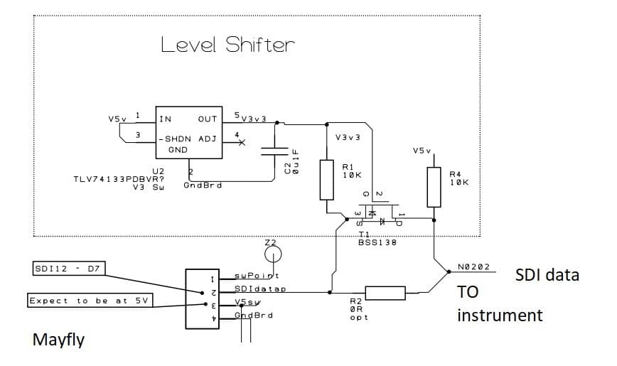
I have come up with an inline plug-in circuit that will do the voltage shifting ( and generate a +12V power and ESD protection) that I’m working on, so just mentioning it here. If anybody is interested in the discussion we could take it to a separate thread.
Attachments:
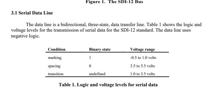
Just an FYI, as I understand the SDI-12 spec, the receiving instrument should receive 3.5V for a ‘0’ or space. The mayfly port is only capable of supplying 3.3V – so it may work for most SDI-12 instruments, and is working for one SDI-12 instrument I’m using
Typically with off-spec issues, things can work on some instruments and then not on others. So hopefully the problem is something simple, but just sharing my analysis.
Attachments:
There is a Mayfly Protoshield rev1 – but I can’t find if its for sale anywhere.
I have one, and no plans for it right now so if you wanted it I could send it to you.
The details are here, but no gerbers. With gerbers it would be possible to order the base boards directly from oshpark.com
https://github.com/EnviroDIY/EnviroDIY_Mayfly_Logger/tree/master/hardware/protoshield
https://photos.app.goo.gl/ocKSN3AuoqvJJx1L8
I have a base board defined in my PCB package, I could look at what it would take to generate a PCB and then you could order it directly.
This would be the simplest, small spacing 2.54mm/0.1″ using,
https://www.digikey.com/product-detail/en/on-shore-technology-inc/OSTVN10A150/ED10567-ND/1588870
but practically speaking, it could be any connectors that you define how they fit round the Mayfly 2×10 connector.
I have a PCB that fits on the analog side – for Electrical Conductivity Stream Disconnect for (which I’m hoping to to write up pretty soon ) so it would look something like this..
https://oshpark.com/shared_projects/WSMDBFEB
Hi Matt,
There is a Mayfly prototyping board, which I should have used for one project, and forgot to 🙂
I’ve prototyped with a basic 2×10 male to male header using wire wrap and soldering to the header. However I cut the 2×10 from a larger length I had, and it became unreliable pretty quickly. For a cable maybe 0.05″ ribbon cable with IDC headers, which I think only come in female (I haven’t checked for male IDC), and then a double male to fit into the Mayfly socket and IDC female socket.
Practically speaking, for an Electrical Conductivity that interfaces to the processors analog pins (J4), as basic as you can get I found the male headers unreliable. I made a special PCB for it. I’m still documenting it going to share it at some point.
The response is great.
For my WiFi/Xbee S6 accelerated updates 2min sampling update every 4minutes the ACK time over 700 POSTS time is between 200mS and 774mS. All POST succeeding 1st attempt.
For my Verizon/Xbee LTE at 15minutes sampling the ACK time is typically 5sec, very occasionaly about 1.5sec, and also 7Sec. For this test it delivered the outstanding readings that weren’t delivered previously, and then the new readings.
I am working on new feature Reliable Delivery, as cellular wireless range can vary and be unreliable. Often though there are periods of greater reliability (wind in the right direction). So if the first POST attempt doesn’t succeed, it is serialized to a QUExx.txt file to be retried when there is a connection.
Over the last couple of days I’m getting very good response when using a WiFi, and the response time for 201 ack is sub 1second.
This is a fast check with 2min sampling time, and SendX=2, so delivery every 4minutes. I get a response typically under 0.5seconds, and occasionally ~ 0.6Seconds. So for 1250 messages all have been delivered, 1st time or subsequent retrys..
For the beta verizon system, with sampling at 15minutes, and SendX=8, that is wireless connection every 2hrs, and timeout of 5seconds, there are burst of successful delivery with ack 201. The ack time is sometimes at about 1.4Seconds, but mostly when successful at about 4.5seconds. So I’m guessing this is something to do with Verizon’s network. I’m going to have to change the timeout back to the 10seconds for better characterization.
Thanks to the MMW team for finding the issues and getting it responding.!!!
Hey good to hear.
I haven’t been able to do a lot of testing, and I was out yesterday but I enabled a laptop computer to monitor one beta system overnight that is using verizon starting at 9pm PST. (though I forgot to add the power cord to the laptop and it turned off after 2hrs !! ). Its sampling at 15minutes, taking 8 readings, and pushing the 8 updates every 2hours, at an offset of 7 minutes. That is at 23:07, 01:07, 03:07. The POST timeout is tighter at 5 seconds, if it doesn’t get a response it records it as a 504. I’ve created a POSTLOG.TXT on the uSD that records all post attempts. If it doesn’t get a 201 it queues the readings and then retrys on the next sucess 201.
Looking at the POSTLOG.txt this morning, it has mostly got 504’s, with a few 201s.
The Debug Log that I got from a POST of 8 readings at PST 23:07pm (2020-08-07T07:07:00-08:00 ) were all 504
Downloading from MMW the .csv file this morning, and looking at the records, a good number 24 readings didn’t make it to the database, but those that did, all made it.
I’ll set up some more testing later today.
https://github.com/ODM2/ODM2DataSharingPortal/issues/483
https://github.com/EnviroDIY/ModularSensors/issues/194
Thanks for the headsup. I was checking yesterday so wondering what the status was. Many thanks
2020-06-19 at 10:41 AM in reply to: Campbell Scientific CS-215 SDI-12 communication issues w/ Mayfly #14257Looking at this posts as a discussion on general SDI-12, I have the Mayfly interface working for a Insitu LT500 Water Level monitor in a prototype capacity.
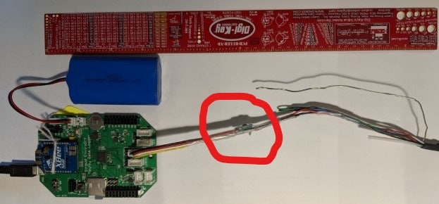
The LT500 requires an 8-36V Excitation, so I put in a series booster, +12V https://www.pololu.com/product/2117, and connected the other end to Grove 4pin JST-PH cable (std one cut in half)

I did use the standard SDI12 lib, and just created a header file for the InsituTrollSdi12.h for the interface. So very easy.Thanks for everyone contributing to SDI-12 to make it so easy.
I’d be happy to post back the InsituTrollSdi12.h if anybody wants.
It does take a little setup on the LT500 mapping the sensor value on polling to where the SDI12Sensors.cpp expects it – though my notes are a bit hazy on what I did.
Since the SDI-12 spec defines clamping excess voltages to ground (lightening/ESD), today I’m in the process of creating a true SDI-12 physical interface with the level shifter BSS138 ~ one side pluggable into a Grove 4pin/5V, and the other side taking the SDI-12 3wires.
Be happy to share the PCB/cct/BOM with anybody interested.
The target is to deliver the results over a Verizon signal ~ thanks to @mbarney for suggesting the Digkey SIM and data plan https://dataplans.digikey.com . It does require setting the apn to VZWINTERNET. Its not as easy as hologram to setup.
Attachments:
I could be needing about 6 Mayfly’s + 1 LTE Adapter Board – where is the best way of placing an order, many thanks Neil
-
AuthorPosts