Forum Replies Created
-
AuthorPosts
-
I had some of the same ~ then for new sensors on a specific site, I found by changing the name and removing the ‘-‘ in the name, the new sensor + started working for me.
Last week I added a new site, had a few problems, changed revisited the site/name slightly, and the I was able to add the sensors.
https://monitormywatershed.org/sites/tu_rc_test04/
I did raise an issue when I first encountered it… it is a critical show stopper bug when it happens.
Here is some new data. I had the FTDI cable connected, and seems like it was influencing things somehow. I cut the RX (always high ~ 3.5V) and that changed the way Q1 is turned on. Still not sure why. I removed the FTDI altogether and repeated the readings.
The Mayfly will now continue operating to V_batt = 3.00V, Proc resets when I drop to 2.95V (motioning with a reasonably professional Meterman 37XR voltmeter).
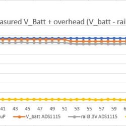
The overhead/buffer difference V_batt &rail3.3V is now about 0.15V, probably mostly the SPX3819.
However it does show that the mega1284 A6 measurement is only linear to about 3.5V.
The 2nd graph shows the difference between V_Batt and 3.3V rail
I’ve added the .xls with the readings.
So just checking, the Vbat voltage range. I’ve an application that doesn’t have a solar panel. I’m trying to figure out 1) can a LiSOCl2 3.6V 19Ahr be used 2) 3*D Mn 18Ahr 3) generically characterize the LiPo measured Voltage,
So I’m finding for some reason there is a need for 0.55V overhead from the processors 3.3V. Seems this the LDO and the MOSFET.
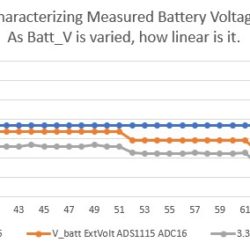
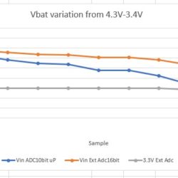
I’ve generated some data, graph below. This is a miniumium load, of the Mayfly taking a measurement every two minutes, and sleeping inbetween. Its measuring the Vbatt through uP A6 (blue line), then ADS1115 through a divider 1M/1M measuring the Vbat (orange line) and also the processors 3.3V (grey line)
I also added a low ESR 680uF cap to V_batt (Digikey 732-9079-1-ND ) to buffer any current pulls. Though under V_batt=3.45V the processor starts to reset.
My method is for an FTDI 3.3 cable to J2. I’ve disconnected J2-4/Vusb and J2-1/DTR. No USB cable. Variable power supply connected to JP1. Then vary the power supply Vbatt, measure externally with a Meterman 37XR volt meter to set the voltage, wait for a measurement to show on the TTY. Then drop the voltage and repeat.
The orangle line is accurate, the blue starts to droop under a real 4.1V, and flattens underneath a real 3.8V, as the 3.3V then starts to droop.
So I’m wonder if you have seen the same and any thoughts on the 0.55V overhead. That kinda eliminates the compact LiSOCl2 battery for me.
Attachments:
I’m added a new capability for the Mayfly to program its internal EEPROM with geographical specific pieces of information.
When a site is visited, this will allow the retrieved uSD card to be replaced with a blank uSD card.https://github.com/neilh10/ModularSensors/wiki/1a-Feature-notes
For multiples sites that don’t have modems, and the readings are retrieved on a site visit by replacing the uSD card, I’m seeing the workflow is that the uSD cards are retrieved and stored together.
The remote site visit workflow would be to keep the the retrieved uSD cards separate from the blank uSD’s. Back in the office, the retrieved uSD cards are read, and each .csv file has unique geographical and node information on it. The site visit could be performed by one person, and then the person reading the uSD and analyzing the data, would have good traceability that uSD readings came from a specific Mayfly/geography.
Just wondering if I’ve covered all information that needs to be stored on a uSD to make it uniquely identifiable. ?
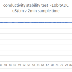
@movingplaid for the basic EC sensor above, and 10bit ADC and running at 2minutes sampling – which is way too fast for a simple DC switched EC sensor got a pretty good result. Graph below.
Next stage is to run it overnight, and for simplicity will graph it on MMW
Attachments:
Hi Robert, I really like your Continuous Logger Post and the installation detail.
I’d be happy to share what I’m doing, and I’ve just finishing up a ModularSensors class last week.
just thought I had posted here, and it hasn’t shown up, so trying again – here are the core details
https://github.com/neilh10/ModularSensors/blob/rel1_dvlp1m/src/sensors/analogElecConductivity.h
https://github.com/neilh10/ModularSensors/blob/rel1_dvlp1m/src/sensors/analogElecConductivity.cpp
Comments and code review welcome.
Its using an analog port, per the original post, and powered by a toggling port bit.
The actual target is a “Relative EC” as a “Stream Disconnect Sensor”
https://agupubs.onlinelibrary.wiley.com/doi/pdf/10.1002/2013WR015158
so I’m not paying attention to the units of measurement, though still calculating them as uS/cm2
Attachments:
Hi Jake
Good to hear about it. I’d be happy to do a PR on it.
One of the other areas I believe for scaling for a group is quality testing. For every commercial company I’ve been with, being a able to test and characterize the functionality – that is how well it works – is a big value add to the end defined release. For anybody who works with embedded software for very long, repeatable builds and testing is a really challenging. So I’ve also defined a release that can be built simply and downloaded. I’ve put it in “examples”, but I think there should be in a “tested” directory or maybe there is a better name for it.
ModularSensors/examples/tu_id01 and is at
(edit oops its changed)
github.com/neilh10/ModularSensors/tree/release1/examples/tu_xx01I’m still not clear on how to manage the repeatable builds with the distributed code environment, but working on it.
Hi Jim. Thanks for the description.
What the ‘ini’ reader does is read a file on the Mayfly microSD card called ms_cfg.ini – in that file is all the configuration information that is specific to a particular node “station” as when the MMW sensor UUIDs are created.
What this does is allow your .ino file to be compiled once to a .HEX, with no custom UUIDs. All the node specific MMW UUIDs are then put in the individual “Stations” Mayfly microSD files.
The Mayfly’s mega1284 is a small 8bit microprocessor, and there is very limited networking capability – not like a linux system that has a lot of generic networking. So no there is no capability to push a UUID back onto the Mayfly.
On MMW I couldn’t find a way of searching for Sites GMI_* it needs the Organization to be first specified.
Hi Anthony ~ thanks for the headsup. For today my desk proto system running at 15minutes intervals/WiFi I haven’t seen any timeouts, all 201’s in the last 5hrs
Matt, sorry to hear the reconstruction issues. Welcome to software development. I’ve got lots of silver hairs from it.
The process of proving or verifying software functionality, improving reliability (however its defined), is a tough and sometimes expensive process. For over all reliability and repeat-ability, you could start another forum discussing best practices. I’d be happy to share my best practice.
For one software consideration you might read this for future methods https://github.com/neilh10/ModularSensors/wiki/Release-downloads
I had one job interview early in my career, this small business had a student do something for him, and then the student moved on. I was interviewed; could I construct from paper listings the program, and then make some modifications to the program.!
At least we have github now, and make copies of the .git. 🙂
I have my desktop development environment, and do accelerated testing (run it 2minute intervals over WiFi). Then when I have stable program, I both label it and uniquely copy and label the firmware.hex. Then I move that out to an outside more realistic “beta” test site (eg 15minutes over CAT-M1) and let the software run under realistic conditions for some time.
Then with no known issues, I move it to the field, That is what has happened here https://monitormywatershed.org/sites/TU-RC-01/
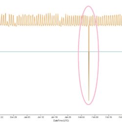
However, for this site, I’m getting anomalies about every month which was a bit beyond my initial testing.
Oh well! Got to work on a local test environment to shadow the field one.
Attachments:
Hi Matt
You’re doing some good characterization work. Thankyou for sharing it.
A basic issue to keep in mind is that all communications can be unreliable as there is complex telecoms infrastructure.An arbitrary wireless placement’s reliability is difficult to quantify ~ distance to cell head, direction of wind, fog/rain etc. A wireless network location needs to be categorized for being reliable.
I use the office based WiFi to attempt to have a reliable reference point. (and I’m still seeing timeouts 504 with data delivery and also some posts not being inserted)
From an industry context, communication protocol retry’s are the only way to provide for reliable data delivery, and I raised this feature request.
https://github.com/EnviroDIY/ModularSensors/issues/194I haven’t managed to implement it in my EnviroDIY systems yet either https://github.com/neilh10/ModularSensors, but its high on my list, and periodically I give me a kick on the butt for not having got it done. Like now. Ideally this type of reliable delivery is implemented early so that overall reliability can be characterized. I implemented another system, and even though networks in rural areas could be down for weeks, the data would eventually ALL be pushed to the server.
I have implemented a Sequence number (EnviroDIY_Mayfly_SampleNum) which increments on the Mayfly side, and then on the monitorMyWatershed it can be viewed, and any missing numbers detected.
So for a field system the sequence number appears to be continuous from Oct/24/2019, https://monitormywatershed.org/tsa/?sitecode=TU-RC-01&variablecode=EnviroDIY_Mayfly_SampleNum&view=visualization&plot=true
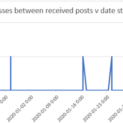
So for this system, running over I think an ATT CAT-M1 modem, there are only occasional packet losses of 1 – see graph generated from .xls file

That said I have been seeing a lot of (504) from my desk workstations – and haven’t dug into why.
Attachments:
-
AuthorPosts

 Welcome to EnviroDIY, a community for do-it-yourself environmental science and monitoring. EnviroDIY is part of