@neilh20
5 days agoForum Replies Created
-
AuthorPosts
-
Thanks for posting. What comes across is its IP20 – ;
A rating of “IP20” (pronounced “IP two zero,” not “IP twenty”), denotes protection from solid objects approximately 12mm in size, such as adult fingers; however, it also denotes no protection at all against liquids.The other issue is that its an Intel Intel Quark® x1000, 512 MB RAM, 1 Ethernet interface – historically Intel is an electric power hog, but that is all dependent on your location.
I take its target market to requiring power available (Intel Quark), an Industrial setting with the DIN rail.
For hot outdoor application, I would think you would want local solar/battery powering and IP62 (or higher eg IP65)- which would be protection from ants/insects and heavy rain failing
https://en.wikipedia.org/wiki/IP_CodeWow – congratulations on deploying. Always a watershed moment to get it in to the real outdoors.
When its easy, it would be fascinating to see the basic parts list, outdoor configuration, power configuration especially with the GPRSbee, and target sensor data collection
Many thanks for sharing.Well I’ve done some design thinking on this. I’ve focused on just generating the +12V. The issue with the Mayfly circuit is that the switched pwr comes from the 3.3V which also powers the processor – and a power hog on the 3.3V_Sw is going to cause a processor power glitch – yes I’ve had them in the past and they are nasty to debug

So I want to generate +12V, and possibly the easy way to do it is with
SUNKEE LM2577 DC-DC Adjustable Step-up Power Converter – available on Amazon.com (amazing)
The design needed for the boost circuit is to be able to switch it on when needed.
The +5V boost NCP1402 does have an enable on it but it is permanently enabled. It is tied to the 3_3VSw – which is powered by the LDO SPX3819 which is rated for 0.5A.
So not very power efficient, drop input voltage (LiPo 4.2V or +5V) to 3.3V and then boost to +5V – but workable
The NCP1402 is rated for 130mA, so that is not likely to cause a glitch on the 3.3V
Ideally I would
cut trace to C13/L1 and tie power line to C7/D3
Then the NCP1402 U3-En SJ5-3 cut & strapped to Port-D22/(3.3_SW) OR another PortSo I wonder it the layout for the Mayfly is easily available to see how the traces are done.
I’ve ordered the $6 SUNKEE LM2577 DC-DC Adjustable Step-up Power Converter and a Mayfly to try it out.
The other option I considered was to use +12V -start with a SLC battery, and then drop the voltage to +5V for Mayfly.
All the switching is done at 12V/SLA low impedance, with an interesting
$15 CWE Arduino Dual Channel Smart FET Driver Board with Current Sensing 8-28VDC
and a switch converter 12Vto +5V for mayfly.
Theoretically it would have been then possible to add +5V/1A cellular phone later – but this would get expensive for power modules and take more design now.One of the reasons I considered +12V is I am using an Olimex-STM32-H407 – which takes +12V, for prototyping modbusm.
Personally I think the STM32F4 family is going to provide a lot of versatility for the future –
http://www.stm32duino.com/ for a lot of small boards now andThe key is a rugged mechanical environmental enclosure, solar power, power switching managed by the SMT32F4xx, and low power sleep capability, and using its unique USB Host capability for pluggable USB modems. This can then communicate with the Mayfly over the XbeePro modules. So that’s the longer term plan.
Hey Goodluck
Sounds like you have got the measurement traceability going. The local water company here installed a German ultrasonic meter, on the recommendation of Siemens. So far it seems to be slightly under-reading the water flow compared to the impeller meter I have, but haven’t done any detailed measurements on it. I’m waiting to see if there will be any visibility of the readings to customers (me).
I’m using 12V and 4-20mA on a project. Its a using the commercial Onset U30-C3G with analog interface and reporting in over cellular. It has a WiFi option.
The 4-20mA interface has been very good, accurate and stable signal across the 12bit ADC.
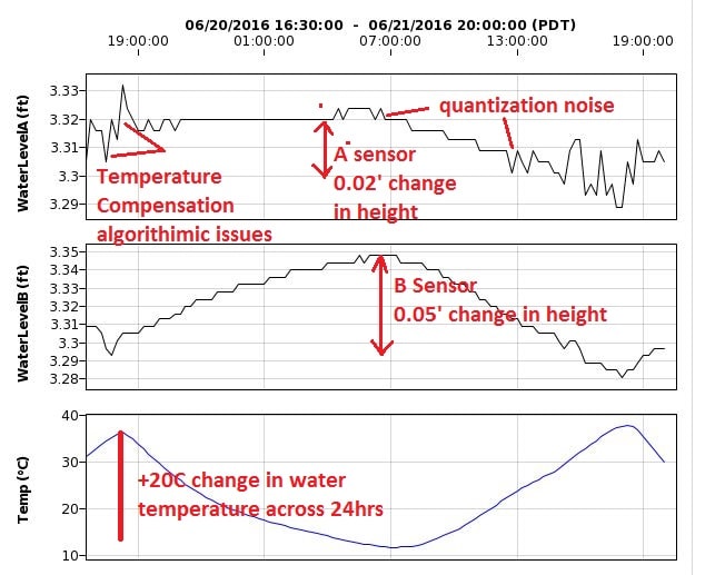
I first tested it with some resistors to see how stable it is.Our issue was accuracy – we wanted to measure changes of 1/100′ or 0.01′. That limited the dynamic range to 10′ depth of water.
So technically the dynamic range is about 10bit- 2**10=1024. Then you need to take into account digital quantization – the accuracy of the ADC and potential slight drifts that can occur. Temperature drift also needed to be accounted for, and potentially there can be a 20C change in temperature across a day/24hr cycle.
I enclose a graph taken from a snapshot of two sensors tied together over 24hrs of pre-deployment testing in a stable 3.6′ water column. Typically I tested in 0.5′ of water, but wanted to test them at different depth. I believe the noise is coming from the sensors – both sensors are the same type of depth gage, but different responses.
The graph demonstrates the value in doing some acceptance testing in known conditions – in this case level water (except for slight evaporation).
You may want to consider how you can generate a 1/16 gallon flow/leak and then monitor the meters over a couple of weeks.Attachments:
Hi Jeff, I think you’ve taken on a difficult challenge with estimating what is exactly ‘0’ at 4mA, and you would want to look at what is a theoritical low flow and can your ADC even detect that.
Just wondering what the history is with having a 4-20mA flow detector in this location.
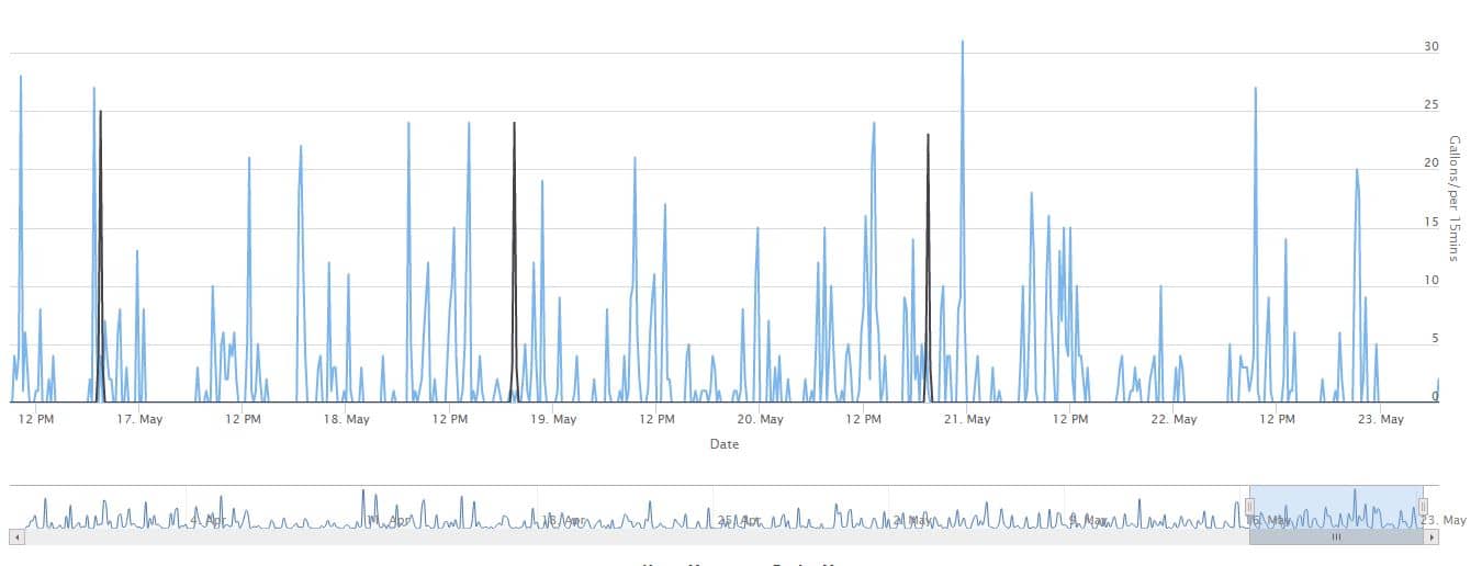
Just to compare it against something I’ve done, for monitoring and leak detection I’ve used a water meter with a gallon clicker – Jerman.com DLJSJ75C.
So every time a gallon passes it closes/releases a relay. Then I have an Arduino SAM3X that measures the clicks. I could publish the code on that if you are interested.
It sends the results to thingspeak – I can then read the data from thingspeak and create a graph. I attach a graph – the blue is the water used on the house water meter, and the black line is the garden water meter.
For leak detection – this is guaranteed to show every gallon and the way I do it is to count over 15minutes.
The actual reed relay closes/opens on 0.1G passing and stays open for the next 0.9G – so technically it would be possible to detect a continuous leak down to 0.1G over some period.The basic issue with looking for leaks at 4ma/ is that the trace ability of the measurements is challenging.
On the 4-20mA side its how accurate is the 4mA to indicate low flow, and how you integrate it, and on your Uno side how accurate is the Vref and how much accuracy can you get from the ADC digitization.
I personally stay away from anything that hasn’t got at least 12bits on the ADC and a good ADC ref. The Mayfly has a good analog monitoring – see its specs. Then you need to understand your analog flow meters and come up with a definition of what is the leak flow rate that you want to catch.So the 4-20mA is useful for communicating over wires over a long distance, and for interfacing to specific types of monitoring equipment.
Sorry to not be more helpful on 4-20mA, but hope the reasoning is visible.
Attachments:
Hey congrats. Very nice.
I’ve been playing with the Particle.io photon as well, nice environment and easy to use.
I was wondering how do you plan on calibrating it and tracking the accuracy of the readings? – perhaps too early to ask that.
I always add a low cost aluminium measuring rule or USGS style manual gauge.I’ve been using thingspeak.com for recording – here is a basic visualization of data from a simple rain gauge I measured – actually using another board – but the Particle photon is so much nicer and I will be using it
https://thingspeak.com/channels/8652The nice thing about thingspeak is its basic data visualization, and you can decide what data to share on a public URL, and also what to keep private for management behind the scenes.
Hi Ben
Thanks for posting and the links. Fascinating and thanks for the status.
I was wondering, does the “Distance sensor” have a memory, can it report all readings if the gateway goes down for a couple of days.
I was wondering is there a schematic of the “Distance sensor ” https://github.com/OxFloodNet – I couldn’t find it to ask the above question
NeilSensors for continuous monitoring are challenging, see this for nutrients
Nutrient Sensor Challenge aims to coax market for next generation instruments
which is an EPA initiate to develop real-time sensors under $8K!!
http://www.epa.gov/innovation/examples-epa-prize-competitions
On the other end of the spectrum for low key community orientated “learning” projects
https://publiclab.org/wiki/open-water
My 2cents for reclaimed water is to look first at your local jurisdiction legal requirements you need to meet, then break it into components. Practically speaking its dependent on the source of the reclaimed water, and what your base load of pollutants might be
1) for volume of irrigation water it may be relatively easy to sense
2) for other nutrients you may start with determining best practices, manual sampling, and on to continuous monitoring.
I don’t think there is a one solution fits all easy answer.Hi All
I was visiting the ArmTechCon/Santa Clara last week and a friend was on the ARM stand showing their CalPoly university project.
It had the basic same concept – using ultra-sonic to measure the depth of trash in a street side trash can, and then with a map displaying potentially multiple locations of monitored trash cans.
I asked if they would be OK if it was posted on this board, and he updated the links for it. The actual CalPoly project description seems to have expired.The hardware they used was
https://developer.mbed.org/platforms/u-blox-C027/Corey says:
Feel free to share the code if you think others would find it useful.
I’ve just published the latest to:
https://developer.mbed.org/teams/Garbage-Collectors/code/SLOTrashHTTP/
https://github.com/coyotebush/trash-mapIt uses Flask, and a previous quote about this was
Flask was nice for handling the HTTP bits of the server. I’ve used it in other projects before and found it straightforward. Fairly popular in
the Python community, I think, as an alternative to larger application
frameworks like Django.So while the project should be considered a “prototype” the components might be useful.
Hey kevin, great to see a sketch.
Some thoughts
1) I would ensure a standard measuring tape on the outside of the tube – make it easy for any site visits by anybody the waterdepth and time of measurement can be recorded and used to validate/calibrate that electronic measurements
2) I personally have no experience with the ultrasonic transducer method – so I would think you want to be pretty clear that it works, and also to define what accuracy of measurement you are looking for. A simple way is to make the equipment and then leave it with a known stable water column for a couple of weeks. Possibly even allow water to evaporate and verify the readings as the water drops.
3) Might be better to move the senors at the bottom into their own protective shielded pipe so that if they ever need maintenance you don’t risk moving the pipe with the water column in it.
4)I would think for your flood location, you want to be aware of the velocity of the water and whether or not the top of your standpipe needs tying into the bank. A visual examination of local conditions for a low velocity location is always best.
Here is a link with some pictures of people installing a pipe in tidal marsh area.
http://tidalmarshmonitoring.org/monitoring-methods-hydrology-continuous-water-level.php
Usually with any electronic sensor the quality of the recordings – errors is the most challenging. Be great if you report on what you find if you do any managed “soak” testing.
Good luck -
AuthorPosts