@neilh20
5 days agoForum Replies Created
-
AuthorPosts
-
There is some onchip references, but maybe not useful. From the manual mega164A_PA-324A_PA-644A_PA-1284_P_Data-Sheet-40002070B.pdf (applies to the mega1284)
Chp 23.2: “<span class=”fontstyle0″>Internal reference voltages of nominally 1.1V, 2.56V, or AV</span><span class=”fontstyle0″>CC </span><span class=”fontstyle0″>are provided On-chip. The voltage reference may be externally decoupled at the AREF pin by a capacitor for better noise performance. </span> ”
However the benefit of the 3.3V is that its +-1% – whereas the 1.1V and 2.56 are +/- ~10%
Hey thanks for the overview. Welcome to the art of jumping in – and learning by doing (my philosophy though I’m an EE graduate) – though its beneficial to bring an engineering basis to analyzing the components, and then plug the components together. The engineering basis can be thought of as a technical story – though for EE graduates we talk about engineering requirements.
I’d suggest looking at how to interface to the Campbell Scientific – that is can you inject some dimension less numbers in some fashion and have it come out the other side somewhere that can be used. Maybe other people know more about it, than I do – but you may want the specific model numbers. I looked at trying to work with a 20yr old CS recently, and concluded it really needed a whole new upgrade – and actually finding the satellite channels for even an upgrade was going to be one challenge.
At the simplest level, if you have some Analog inputs available on the Campbell scientific, then it could be case of “extending” those inputs remotely, and scaling the input voltage to your snow depth units.
So then on the snow depth sensor, how does the sensor present its measurement – from other posts on the board it seems you are trying to measure some voltages, so may be that is the snow depth measurement. So then what is the range of the depth measurement. you want to make and what is the dynamic range and resolution on the sensor. That is the sensor might have a dynamic range of 3meter with an accuracy of +/10cm, but actually you are only interested in if there is 0-5cm increase of snow in a 1hour period.
Maybe some other people have better insights – but that would be my first guess at defining what you want to achieve
Gosh Brandon, I successfully used the 900Mhz modules about 15years ago with the TinyOS framework.
Seems you are thinking of using it in a Peer-2-peer arrangement, possibly in a mesh configuration. A lot of options.
I wonder what your back ground is – cause its sort of like jumping into the deep end, and you may wanna flesh out your plan – what your basic intent is. Is there any reason XBee Pro S3B, and not a LoRa in a peer to peer? (Digi XBee LR).
From what I remember, for some of the Xbee’s you can configure in a point to point mode, and then it looks like you are sending data down a wire. The critical issue is that through the XCTU you configure two units to look like a wire – start with XCTU and data sheet of the devices. Of course if you are sending in JSON one end , then you need to have a JSON parser the other end. So that means you want to design your JSON packet. Of course JSON is bulky and thats where if you use the simplest binary numbers, it could fit in a LoRa packet, thats why I bring up the differences.
Hi @dani68k, welcome to EnviroDIY.
I’ve not got any experience on the ATmega32u4, and as a small AVR processor I would think you would need to customize your development for it. SDI-12 bit banging is very sensitive (unrelaible) if the timing isn’t configured right. Possibly using the USART would be better for timeing, but configuring that is another story. Also needs compute the CRC in the allocated time.
My approach would be to separate the development in to two parts divide the problem into smaller testable parts – one proving the SDI-12 protocol/ response and the other reading the sensor over I2C.
Say every time there is SDI12 request – after any response to the host, flash the led for a correctly decoded CRC and a different sequence for failed CRC – that way you know if the basic request msg was received OK.
Then for successful request return an incrementing number, that way you can see that all the protocol is working, and the response CRC is being correctly calculated.
Then separately, set up program so that say every 10seconds it reads the PH sensor, computes the units correctly and displays it with print the basic format you want to send as well as human readable format.
Of course with realtime protocols like SDI12, and reading a sensor, prints do impact the real-time nature and may cause realtime bugs just using them. Having the USB interface does allow prints to come out, but also implies you need to understand how the queue is maintained inside the 32u4
Unfortunately, its easy for many things to go wrong, and sometimes it takes focused analysis on the data flow to see the way it might work, and then tweak the program to work that way.
When asking for help, you may want to be explicit as to which library’s/systems you are using, devices you are using and do all the work for any reader with links.
good luck with it
Thanks to @ptomasula for fixing https://github.com/ODM2/ODM2DataSharingPortal/issues/658
If I understand it right, the internal redirection for POST to MonitorMyWatershed.org/api/data-stream/ HTTP/1.1 got broken with the upgrade to v0.15.0, and a http response of 301 was returned, which ModularSensors doesn’t handle. Of course its not a good idea for ModularSensors to handle a redireciton, as its expensive in power.
Given the failure, and that my fork has built in reliability https://github.com/neilh10/ModularSensors/wiki/1a-Feature-notes I’ve been monitoring the responses from 4 systems and characterizing the server after the upgrade.
I’m afraid the server seems to have degraded after this upgrade, I wonder if anybody else is seeing different results after the upgrade.?
I’ve put my results here https://github.com/ODM2/ODM2DataSharingPortal/issues/661
A previous reference is here https://github.com/ODM2/ODM2DataSharingPortal/issues/552
I’m happy to run this against a staging server if available.
@dan-wachusett Gosh just seeing this – seems like you got that Keller CTD.
Just wondering did you follow the advice given from https://www.envirodiy.org/topic/keller-ctd-sensor/#post-16332
Partly its decoding the layers of software. The keller protocol is used to access the Keller CTD map. I find it most helpful to compare and trace how different keller instruments are handled by the enviroDIY keller. If you only have one Keller Instrument on your line, then you are getting a response from that instrument – you may need to interpret the data that is coming back and find a path to getting working readings.
2023-05-24 at 3:59 PM in reply to: Power usage of Mayfly1.1 with Hydros 21 cTD and LTE BEE cell modem #17842Some recent posts here explain the current difficult environment for calculating power usage on the mayfly as its dependent on a fast response from the server.
https://github.com/ODM2/ODM2DataSharingPortal/issues/649#issuecomment-1561690674
My implementation is to ensure that there is sufficient reservoir of power in the battery for taking sensor readings, and when the battery power is “low” (3.8V) not to use it for Modem Communications. My reliable delivery algorithm POSTs the reading to MMW, and if it gets a bad (not a 201) then stores it to a queue on the uSD. Only if it gets a good 201 ACK from the server, it then attempts to POST all the historical queued readings.
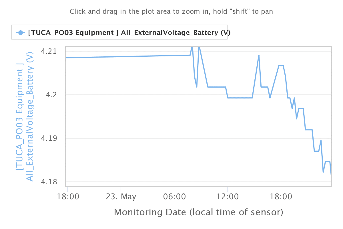
On experiencing a recent virtual month long outage on the MonitorMyWatershed the voltage response on the battery can be seen here
https://monitormywatershed.org/tsv/TUCA_PO03/4805/
as it attempts to push the historical queued data to MMW however the biggest user of power is the 504 timeouts of ten seconds while waiting for a non response from MMW.
Attachments:
Well, I’m back at my desk, with a Mayfly and powered it up, and I’m posting to
Host: monitormywatershed.org
and getting
— Response Code — 301 waited 326 mS Timeout 8000
If I change it to
Host: data.envirodiy.org
— Response Code — 201 waited 577 mS Timeout 8000
From https://github.com/ODM2/ODM2DataSharingPortal/issues/542
aufdenkampe commented on Dec 20, 2021
so, the main host URL that you should be using on devices is monitormywatershed.org. For a couple of years now, data.enviroDIY.org is just a DNS alias that will get redirected to monitormywatershed.org, even for POST requests from devices.
However it seems I got out on the “bleeding edge” because somehow
https://github.com/EnviroDIY/ModularSensors/blob/master/src/publishers/EnviroDIYPublisher.cpp#L21const char* EnviroDIYPublisher::enviroDIYHost = “data.envirodiy.org”;
Also seems discussed here
https://github.com/ODM2/ODM2DataSharingPortal/issues/316
@aufdenkampe @heather @srgdamiano – just wondering where the source of truth is for this URL. ?
https://github.com/ODM2/ODM2DataSharingPortal/issues/6582023-05-08 at 1:02 PM in reply to: Power usage of Mayfly1.1 with Hydros 21 cTD and LTE BEE cell modem #17794@rogers1313 gosh its all depends on the software you are using – what’s the version of software and the source. Since its open source software and hardware, and you can look at the software – its possible to guestimate those answers. Then since its software that causes the most power usage, it needs testing.
For a turnkey system, assembled off the shelf, those are reasonable questions to ask (and have tech support pay for).
For the solar being unavailable due to a storm – I use a target figure of two weeks.
I’m a fan of ModularSensors software and also a critic, with ways of solving the problems. I believe i’m one of the few people to publish the power usage I’ve got..
The Mayfly 1.1 is better at battery voltage measurement than the 0.5, but read some of my blogs on measuring battery voltage.
The standard release transmission software doesn’t have reliable message delivery built in, and the standard software is also IHMO really really really bad at managing power.
The simplest way of answering your question – build the system you want, delivering readings to MMW, put in a voltage measurement off the battery, and then let it run for 1week or 2 weeks and see how the voltage drops on the battery. If possible share the results here as well.
From my measurements, the biggest user of power is posting to MMW. MMW in my experience has a wide range of of how long it will take to respond, including no response. I default to a timeout of about 20seconds for a no response, but it can respond with successful POST ‘201’ in as little as 0.4Secs.
I have shared multiple postings of my power usage measurements, and what I’ve done to make the power usage more efficient – and in the end it depends on your application and how reliable you need it to be –
Just my 2cents.
I wonder if there has been further insight.?
It seems a real challenge to phrase how to have real world reliability. It seems to be such a hard concept to discuss and define how to get there. Its a standard Computer Engineering problem, and it typically requires a commitment to make it happen, and a reference model to test the implementation.
-
AuthorPosts