-
Shannon Hicks wrote a new post 10 years, 1 months ago
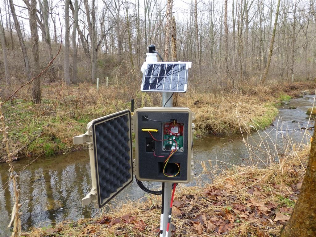
Our Arduino datalogger designs have gone through a few improvements since our original models four years ago. This past year we refined the design even more and have come up with our most rugged and reliable […]
-
Shannon Hicks wrote a new post 10 years, 5 months ago
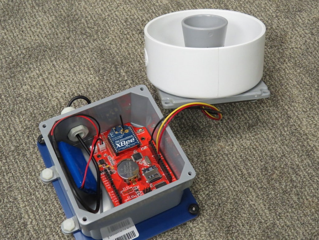
We have been using submersible pressure transducers for water level measurements for many years, but some of our installations are in areas with very shallow water that might freeze during the winter. Most […]
-
@shicks Could you post a bigger image of the test/installed site? And perhaps some sample data? Also info on how the sensors are doing through the winter, would be helpful.
I think I want to build and deploy a couple to test for potential use in community driven local flood monitoring and forecasting in the lower Snoqualmie Valley (outside Seattle).
http://svpa.us/
http://floodzilla.com/-
That photo was from a temporary test setup, so I don’t have more pictures. I moved the PVC pipe to a more secure mounting to survive higher flows. The ultrasonic sensors, along with all of our other sensors and logger circuitry, are performing perfectly this winter, even with air temperatures below 0 degrees C a few times. I’m still running a few experiments with various ultrasonic setups, so I’ll share that data when I’m able to make a conclusion.
-
Hi All,
Really cool stuff that is going on here with the DIY Utrasonic Water Depth sensor. I see how being able to construct something like this on a tight budget is extremely important for increasing stream gauging data.
OnSet makes the HOBO U20L pressure transducer/datalogger combo
(here: http://www.onsetcomp.com/products/data-loggers/U20L-04)
for about $300 (another $200 for the software and PC connection hardware). Besides the fact that the utrasonic water depth sensor can be mounted above the water surface for collecting stage data, are there any other advantages that it has over something like the U20L, such as cost or accuracy?
Thanks!
-Grant
-
This is a good topic for the Q&A forums. Start a thread over there and we can continue the discussion there.
-
-
We’re going to try to build a water level sensor (ultrasound) using your design. But we’re going to need some help. For example, when I Google the Seeduino logger board kit, it says discontinued. And when I try Arduino FIO, I get a whole bunch of different products.
Any chance you could post a list of materials including where we purchase each and a product number? For the off-the-shelf stuff like the sealed plastic j-box, the size would be a great help.
Then a close -up picture of the box with all the components labeled.
Lastly some sort of block diagram showing the connections between components?
If these are already posted somewhere within the website, just point me in the right direction.
Thanks,
Phil
-
-
-
We’ve had really good results with the Decagon CTD sensor. It provides water depth, temperature, and conductivity, all for less than $500. It has a depth range of up to 10 meters and has a resolution of 1 millimeter. It provides data output in either SDI-12 or serial output, both of which can interface nicely with our loggers.
-
Hi Shannon,
I’m wondering if you have an opinion about the minimum depth a CTD reliably works in. I need to measure depth in a small custom made flume and the water depth is rarely above 1 cm. I’ve used CTDs in bigger streams. Thanks.
-
-
@sollins Looks like Seeed has revised their Seeeduino Stalker design since the v2 shown in @shicks build.
http://www.seeedstudio.com/depot/Seeeduino-Stalker-v3-p-1882.html
-
I have dozens of Seeeduino Stalker v2.3 boards, and we have been using them for a few years now. But they were discontinued last fall and replaced with the new v3.0 model. We will not be using the v3.0 version, for a variety of reasons, so we are currently testing and evaluating other board options. The Fio is only handy because it has an Xbee socket, but it has no RTC, solar charger, or memory card slot. We haven’t developed a tutorial for how to build a stalker 2.3 based logger since those boards are nearly impossible to find now.
-
I am curious as to why you will be staying away from the v3.0 Stalker boards. What disadvantages do you see compared to previous versions?
-
-
Okay, I ordered a MB7040 I2CXL-MaxSonar-WR sensor [I like the i2c interface and don’t need mm resolution] and wrote up a bit of a concept paper for what I’m hoping to do.
http://toms-wow.blogspot.com/2015/01/open-source-crowd-source-stream-gauge.html
-
That sensor may not be the best option for you, head over to the Sensor forum, start a thread there and I’ll elaborate.
-
-
Sam, that’s a really good question, ask it over in the “Dataloggers” forum and I’ll answer it there so other people can find these discussions more easily.
-
Been working on my prototype using an Particle.io Photon and a and have been posting about it over in the Particle.io community forums.
https://community.particle.io/t/i2cxl-maxsonar-mb7040-examples/17971/7?u=tsayles
-
I’m a high school intern and my company wants me to create one of these. Could you post some schematics so I can see how you did this.
-
The board we used in the photos (Seeeduino Stalker 3.2) isn’t available anymore. I have a colleague who was going to post a full writeup tutorial for this ultrasonic logger build, but since no one can replicate it due to the obsolete hardware, it got put on hold. Once the new Mayfly board is available (very, very soon), we can do a tutorial of how to interface it with the ultrasonic sensor. Stay tuned!
-
Hey,
I have ordered an Seeduino v2.3, Maxbotix 7389 and a gprsBee rev. 6. Then I found this page ,-)
Nice to see, that these three parts are already in use together …Steve, could you please provide some more information about your setup and software?
Thanks, AnselmPS: The stalker v2.3 was still available somewhere in china with the solar cell, battery and waterproof housing…
-
I’ve been lurking here for sometime, but have just had to sign up! I’m based in the UK and am looking into creating a similar water depth sensor here – I can’t buy the Mayfly as Amazon.com won’t ship it to the UK and its not available on .co.uk unfortuntely 🙁
I just wanted to know though, are you working on the writeup for the Mayfly board?
-
-
-
Hello,
Since the Seeeduino is discontinued and the Mayfly is not available in Estonia, do you happen have any recommendations on a replacement that is available in Europe. What was the approximate running time of your setup? How long would your battery setup last in northern temperate zone with winter temperatures down to -20 C. If you would dump the communications? Would using the Arduino mini pro make a difference? Do you have any experience?
-
We have been field-testing various configurations of the ultrasonic station and wanted to be sure we had the best design before publishing the instructions. Some colleagues and I are having a build session later this week where we will be assembling several Mayfly ultrasonic sensor stations, and our goal is to make a tutorial out of the photos and notes they take, so something should be posted soon after that.
-
I am interested in constructing several of these depth sensors and deploying them in runoff detention ponds at cattle feeding facilities. I was wondering if you had a recommendation for a different board that has the same capabilities as the Seeeduino Stalker v2.3?
Thanks is advance,
Scott
-
Hi Shannon,
If you still have it, could you please share the code that you used for this project?? I have a spare Seeeduino Stalker laying around and it would be great to put it to use, but I am not the most talented with coding. Thanks
-
I would have thought that the beam width of the sensor is too wide to put in a pipe. How long is the pipe you are using and did you have problems with longer lengths? Nice work and thanks for posting this.
-
No, the beam width is very narrow on the models we use, so it doesn’t have a problem in pipes that are 4 or 6 inches in diameter. I experimented a lot with different diameters of pipes and different lengths until I found the right combination that worked for us. Later Maxbotix published this page which nicely summarizes the same findings I got. https://www.maxbotix.com/Tutorials/124.htm
Basically, use a continuous piece, no corrugations, seams, or obstructions along the sides (like condensation and spider webs).
-
-
-
Shannon Hicks wrote a new post 10 years, 5 months ago
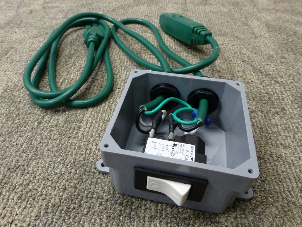
I recently built a device that is very useful but is hard to find commercially, and even information was scarce about how to build one myself, so I’m posting the details here in hopes that it helps anyone who […]
-
Shannon Hicks wrote a new post 10 years, 6 months ago
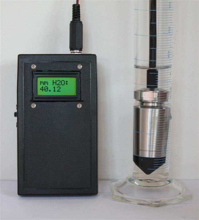
We have several dozen pressure transducers deployed in wells or in streams to measure water level, and sometimes it’s helpful to read the water level directly from the sensor. This model of sensor has an analog […]
-
What’s shown in the photo is a basic analog-output pressure transducer made by Keller-America. It’s been awhile since I checked the price on them, and the ones we used were part of a deeply discounted surplus lot. I think they are usually around $300 or higher, depending on the precision and type of output signal.
-
What model of sensor (provider) do you use for this purpose ?
Do you have an idea of the cost ?
Thanks
Francois
-
-
Shannon Hicks wrote a new post 10 years, 7 months ago
These instructions were written to help teachers and students get the necessary software installed on their computers in preparation for our Introduction to Environmental Sensing workshop. If you want to try th […]
-
Shannon Hicks wrote a new post 10 years, 11 months ago
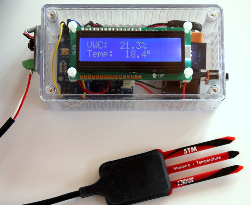
Whenever we install a sensor in the field, it’s always helpful to make sure it is reading properly before connecting it to the datalogger. Having a display to show the live data from a sensor is also helpful […]
-
Our Github site is already active, you can see it here: https://github.com/StroudCenter
But I haven’t written up a tutorial for this sensor display project yet. If you’re good with code and the LCD hardware, take a look at the SDI-12 library examples and you should be able to replicate it pretty easily.
-
+1 from me for a “how to build for dummies”, would be really appreciated
-
Do you have some sketches or schematics available of the hardware? I wonder how you wired SDI to the Arduino.
-
Wiring the sensor to the Arduino board is fairly simple, just connect the SDI12 sensor data line to a free data pin (like D7), connect the sensor power wire to Vcc, and sensor ground to GND. Then just use the sample code provided with the SDI12 library to poll the sensor for data and/or change the channel number. To use a pushbutton on the box for triggering a sample, just have the code sit in a loop looking for a button press, then when it sees the button press, enter the SDI12 sample function that’s shown in the example code.
If you want to avoid the SDI12 stuff altogether, for Decagon sensors you can just set the sensor to channel 0 and it will output a serial TTL string each time the sensor is powered up, so you can just use the momentary button press to power the sensor, capture that string and parse it.
Either method should work fine. I can provide example code for either if you’re interested.
-
Shannon, I would love a copy of your example code for both SDI12 and serial for the Decagon sensors. I’ve got several CTD-10’s that I”m including in a wireless sensor network and would like to use them with an Arduino Mega, but we haven’t worked with SDI12 yet. Thus the code would be greatly appreciated.
Thanks,
Stephanie-
If you’re using CTD-10 sensors, you’ll need a way to connect their 3.5mm stereo plug to your Mega. Once you’ve done that, the code is pretty straightforward. I recently posted an example sketch (http://envirodiy.org/topic/arduino-datalogger/#post-1834) that polls 6 different Decagon 5TM soil moisture sensors that are all connected to the same SDI12 data pin. To use the code with CTD sensors instead of 5TM sensors, you can just change out the one 5TM sampling function for a CTD sampling function. Have a look at that example and see if that’s the kind of functionality you’re looking for, and if so I can post a version that’s specific to the CTD sensors. That example sketch doesn’t do any logging or saving the data, it just grabs the data from the sensors and prints it to the serial monitor every minute. If you want to timestamp your data and/or write it to a memory card and/or transmit it via a telemetry module, then something like the Mayfly would be a good option.
-
-
-
-
Dear Shannon,
is there a small tutorial (with parts, wiring and code) for this nice project? It would save me lots of efforts if I could just jump into this without going through all the initial research and trials. So far, I could not find it here and neither on GitHub.
Thank you so much.
Cheers. Conrad-
I originally built this in 2011 using an Arduino Pro board from Sparkfun and a standard 2×16 LCD with a LCD-SPI backpack interface from Adafruit. I used a clear enclosure because we wanted to be able to show people what’s inside, but the case isn’t waterproof so using it in the field isn’t a good idea. Now I make them using the Mayfly and a the waterproof enclosure that comes with the starter kit. I also use a different display that connects right to the Grove ports on the Mayfly, so the whole thing only requires: a Mayfly, battery, enclosure, display, 3.5mm stereo jack, and a momentary pushbutton. The code for interacting with a SDI-12 sensor can be found on our Github repo: https://github.com/EnviroDIY/Arduino-SDI-12
-
-
Any idea when your Github site will be up and running?
-
Shannon, I am currently testing the SDI-12 code to connect a Decagon CTD-10 to an Mbili board. According to their specs, they use the same processor (ATmega1284p) and clock speed (8 MHz) as the Mayfly. Using only a “carriage return”, when I hit “send” I get the following back in the serial monitor:
0M!
00013
0D0!
00+192+23.5+136However, when I hit “send” a second time, I get the following:
0M!
00+192+23.5+13600013
0D0!
00+209+23.4+135As you know, the “00013” at the end of the second line should be return on a line of its own, without all the data (i.e., 00+192+23.5+136) in front of it. Note that the returned data is the same as the previous measurement (00+192+23.5+136). I’ve tried all the different configurations of “new line, carriage return”, “new line”, “carriage return” with the serial monitor, and both “carriage return” AND “new line” returns the data listed above on the second time I hit send and any subsequent sends. Only the first send returns the correct data. It’s like the serial buffer isn’t flushing from the last 0DO! (“request data from address 0”) sent.
Looking at the code, it does appear that the mySDI12.flush is included after both the “take measurement” request (0MO!) and 0DO! (data request) so I’m not sure what is going on. As I mentioned, the clock speed and microprocessors are the same between the Mayfly and Mbili. I did manage to get the code to work correctly on an Arduino Uno.
Do I need to increase the “delay” time or something? Can you please advise?
Thanks!
Stephanie-
Try changing your CTD address to “1” or anything other than 0. The sensors sometimes give slightly different outputs when they are configured as channel “0”. If that doesn’t fix it, I can send post some sample code that I use for interacting with the CTD sensors. However, we are currently in the process of rewriting most of our libraries in order to implement a new modular sensor method, so some of my previous examples might be broken now unless you use the older libraries.
-
-
Dear Shannon,
I am going to build this using Raspberry Pi, MPS-2 (SDI12 sensor) but without using any SDI12 adapter. I could not find any code for programming and how to establish the connection anywhere. Will you please help me to do this?
Thank you so much.
-
-
Shannon Hicks wrote a new post 11 years ago
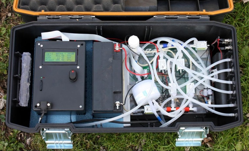
After having great success with the laboratory multi-chamber soil respirometer system, we built a portable version that could be deployed in the field for in-situ measurements. It still uses the same Licor […]
-
Shannon Hicks wrote a new post 11 years, 2 months ago
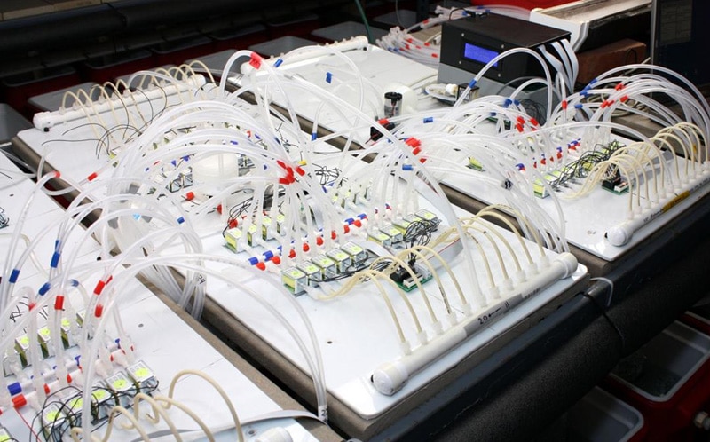
Commercial systems that measure carbon dioxide for soil respiration experiments can be very expensive, but we built one for a fraction of the cost. The controller is based on an Arduino Uno, with a datalogger s […]
-
This looks awesome! Would love to build something similar for an experimental multi-level soil-gas sampler. Would you be able to post a list of components and a basic connection scheme somewhere?
Cheers
Phil -
Hi,
Is it possible to have more information on this soil respirometer you’ve developped?
Best regards
-
We have an old PP Systems multi-channel unit which I would like to adapt based on your system. If you have any extra info that would be super
thanks
davey
-
-
Shannon Hicks wrote a new post 11 years, 7 months ago
One of the biggest challenges when building your own environmental monitoring instrumentation is how to get the sensor cable into the waterproof box with the logger. There are several different methods, but I […]
-
Shannon Hicks wrote a new post 11 years, 9 months ago
One of the most important things to consider when deploying devices outdoors is what type of enclosure you’re going to use. Many designers say they focus on finding the ideal enclosure first, then they design […]
-
Shannon Hicks wrote a new post 11 years, 10 months ago
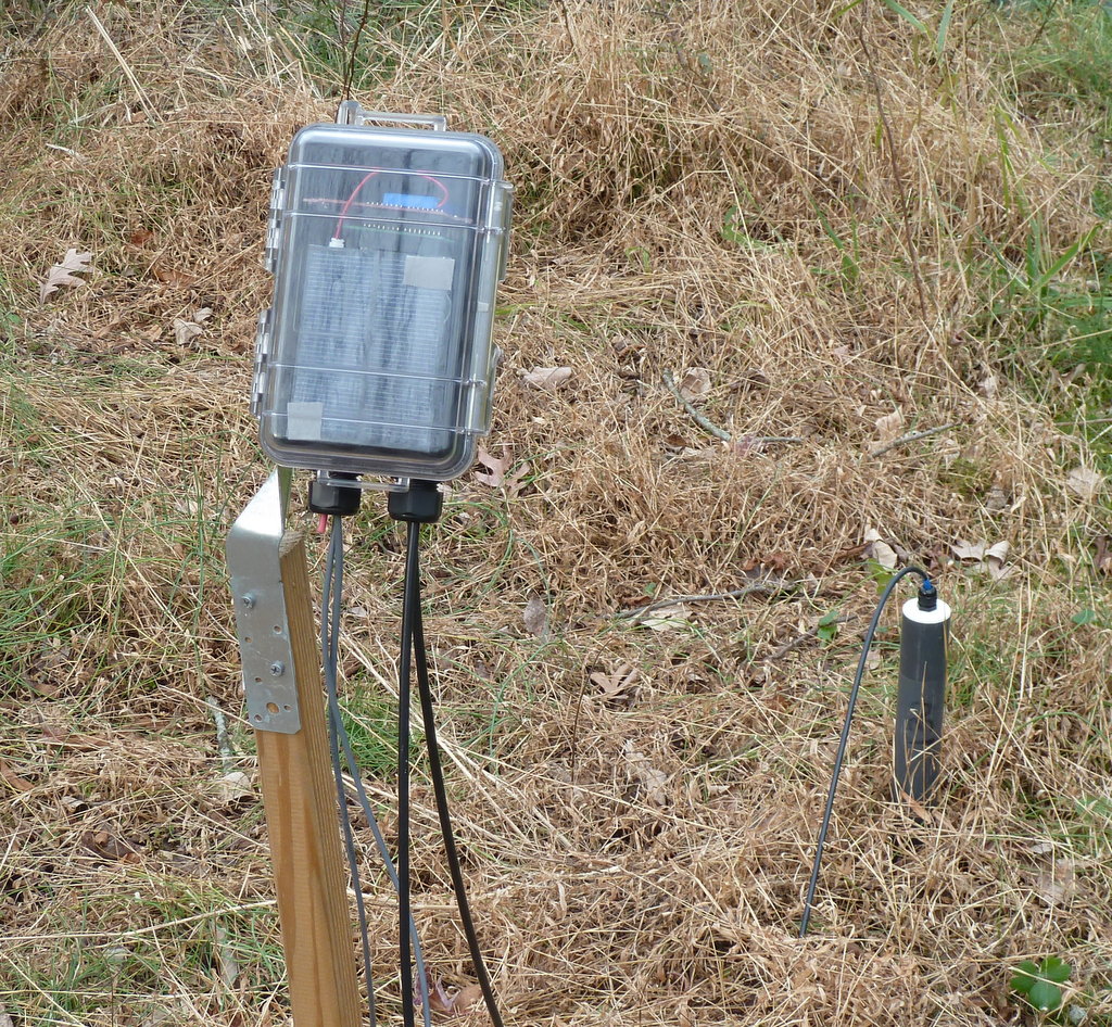
We have had a number of Arduino dataloggers deployed for a couple years now. The first ones were based on the Arduino Pro boards and a datalogger shield from Adafruit. Our newest version is based on the S […]
-
Shannon Hicks wrote a new post 11 years, 11 months ago
I have had several questions lately asking what is the best way to prevent corrosion on the datalogger circuit boards. Even if your boards are deployed in a waterproof enclosure, they will be subjected to high […]
-
Shannon Hicks wrote a new post 12 years, 1 months ago
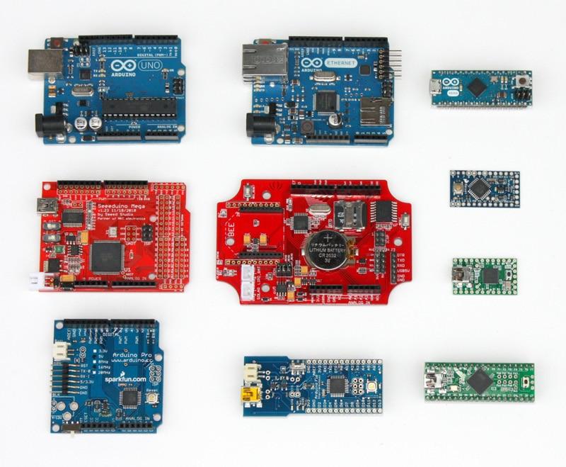
If you are new to Arduino and are wondering what you need to buy to get started with making your own datalogger, things have just gotten a lot easier. We are big fans of Adafruit Industries, maker of the Arduino […]
-
Great place for more Arduino tutorials here as well:
-
-
Shannon Hicks wrote a new post 12 years, 1 months ago
Arduino Electronics PlatformArduino’s home pageAn introduction to ArduinoThe most common hardware used with ArduinoOnline Resources, Tutorials, ProductsArduino forumForum for Adafruit Industries, an open-source h […]
-
Shannon Hicks wrote a new post 12 years, 1 months ago
Welcome to our blog on dataloggers, sensors, and other open source hardware projects. We have created this site as a way of sharing our ideas, designs, and source code so other researchers and hobbyists can […]

 Welcome to EnviroDIY, a community for do-it-yourself environmental science and monitoring. EnviroDIY is part of WikiWatershed, an initiative of Stroud Water Research Center designed to help people advance knowledge and stewardship of fresh water.
 New to EnviroDIY? Start here

How well does you LiPo hold up under extreme cold? What is you data transmission rate? I know in the one I’m working on for NWS I’ve had to put the 2560 and the Xbee 900HP to sleep when not in use to conserve power. We are looking at a 7.2aH SLA battery with solar and regulator.
I’ve had loggers out for several very cold winters now, and I haven’t had any issues with the LiPo batteries due to cold temperatures. The only times I’ve had problems was using them in clear enclosures during the summer because the inside of the case turns into a mini-greenhouse and heats up the batteries (and the logger boards), resulting in erratic behavior of the board and occasional swelling of the batteries. But since we switched to opaque enclosures, I haven’t had any problems in the summer heat.
Do you have any more details or code that you might be prepared to share. I am struggling to create a sketch that will fit on stalker when using a gprsbee to send data, using the standard libraries.
Steve, when I first read your comment I was a little confused. I haven’t used the stalker board before, but I was under the impression that it was a ATmega2560 and not a 328P. I couldn’t figure out why you had code constraints…….
I spoke offline with Steve Hicks about the 2560 logger board I had done. If the community thought it would be useful I could redesign that to be more useful to this community and make it available. I would just need to know what the most prominent portions of the stalker or other board needed to be implemented and what the size constraints might be if any.