Forum Replies Created
-
AuthorPosts
-
Email me your sketch and I’ll load it to a v0. 5b board and see if I can recreate your issue.
Are you using the new sim7080 directly plugged in to the Mayfly, or are you still using the LTEbee adapter board from your old Digi hardware in between the sim7080 and the Mayfly?
We haven’t used that sensor at Stroud, but after looking at the spec sheet, I don’t see why it wouldn’t work with one of our newer Mayfly models that generates 12v. You’ll need a Modbus interface if you want to use that protocol, so either building your own or using the one we’ll be releasing soon. For SDI-12, it should work directly connected to the Mayfly, though you might need to level-shift the data line. But the software-side of things is a question for @srgdamiano since she’s the one who writes the libraries and code for all the Modular Sensors stuff.
The Mayfly board is not a I2C slave device so it does not have an I2C address. The easiest way to transfer data between Mayfly boards would be to use UART like serial or NewSoftSerial.
We’ll be making an announcement next week about the release of the RS485 board, along with updates to the latest Mayfly design which includes good news about the 12v boost option. We’ll also be making some updates to the website to make it much easier for people to see the when and where all of our products are in stock, release dates, compatibility charts, and frequent updates on product development status.
2022-01-17 at 12:12 PM in reply to: How to change the default setting of 5 min data send interval #16278Changing the interval in that line should work, unless you’ve got something else in your code that’s’ interfering with that. What example sketch did you use for your code?
As for delayed transmission of multiple samples, we haven’t felt the need to do that on any of our stations so it’s not a feature we’ve implemented in our code, but I think there are a few members here on EnviroDIY who have written their own code for sending multiple samples. One of the new additions to the Mayfly v1.0 board is that it now has a separate 8MB flash chip to allow users to write data to a non-volatile memory other than the microSD card (or in addition to) so that you could store that 5 minute data on the flash module but only transmit it and put it on the microSD card every hour. Or write it to both every 5 minutes, but only retrieve it from the flash module on the hour when you want to transmit it. I don’t think we’ll be writing any code to do that anytime soon, but the hardware feature is there if someone wants to implement it.
Unfortunately, there’s currently no way to trim out unwanted datapoints from MMW, but perhaps @aufdenkampe can comment about future changes to the site that might allow this.
2022-01-16 at 10:54 PM in reply to: How to change the default setting of 5 min data send interval #16272The transmission rate is determined by whatever you put in the sketch of your logger. I don’t know what sketch you’re starting with, but if you’re using one of our examples that we include with the ModularSensors library, then there’s a line about 50 lines down that says this: const uint8_t loggingInterval = 5;
So 5 is the number of minutes between transmissions. Change that number to whatever your desired interval is, keeping in mind that more frequent transmissions will use shorten your battery life, especially if you’ve got power-hungry sensors or minimal solar exposure.
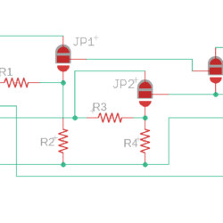
Sounds like modifying your Grove cable to connect the resistor pair to your differential input is your best bet. Here’s a schematic of the multi-purpose screw terminal board if that helps. The gray area on the 3 solder jumpers in the schematic shows the default position of the jumpers. If you’re putting resistors in R1 and R2, you’ll want to change JP1 to the res-div setting. Were you successful at moving the solder blob?
Attachments:
Hi Matt, sorry I didn’t see your original post from last week. You are correct in how the resistor divider works, we have several sensors that have a 0-5v DC output, so dividing it in half makes it safe to read with the 3.3v-based circuitry of the Mayfly’s ADS1115. However, you can also use mismatched resistors to create a divider for something like a 0-12v signal too.
Are you sure you need to use differential measurement of the sensor analog output? Many analog-out sensors have separate power and signal ground lines, but sometimes the manufacturer says it’s okay to connect the signal and power ground wires to the same point. If that’s the case, then you can use the screw terminal board as it was designed by changing over one of the solder jumpers (like JP1) and adding matched resistors to R1 and R2. I haven’t used that particular Turner turbidity sensor, but all of the other Turner sensors I’ve used have allowed me to connect signal ground to power ground.
But if you’re sure you need to use differential measurement, then there’s no easy way to use the screw terminal board since the divider circuitry is based on using the ground pin from the Mayfly as the common wire for the divider. You could modify your board by either cutting traces or by hacking/splicing the Grove cable between the screw terminal board and the Mayfly and adjust which wires go to where, but using a common ground would be a much simpler approach if that will work with your sensor.
-
AuthorPosts

 Welcome to EnviroDIY, a community for do-it-yourself environmental science and monitoring. EnviroDIY is part of