@shicks
8 hours agoForum Replies Created
-
AuthorPosts
-
Yes, you can buy the small case separately, in ABS plastic either with a clear lid or an opaque lid: search the internet for RP1095 or RP1095C and you’ll find multiple vendors.
There’s also a new version with mounting flange feet if you’re planning to mount the case somewhere where having the flange would be helpful. Those are model RP1095BF and RP1095BFC
And if you’re going to be mounting these boxes out in the sun for multiple years, you might want to use their new polycarbonate plastic versions instead of ABS. They’re a little more expensive but will hold up longer if you’re using them by themselves instead of inside a Pelican case. They are models RP1090, RP1090C, RP1090BF, AND RP1090BFC
The Mayfly vertical microSD memory card adapter boards are currently not available separately, but we do offer 5-piece set of them in our EnviroDIY shop.
The Arduino IDE 2.0 is still a beta release and is so new that we haven’t done extensive testing to make sure all our EnviroDIY-related instructions, libraries, and sketches work perfectly. So I would recommend you use the regular release of version 1.8.13 (available here: https://www.arduino.cc/en/software) instead of the beta version.
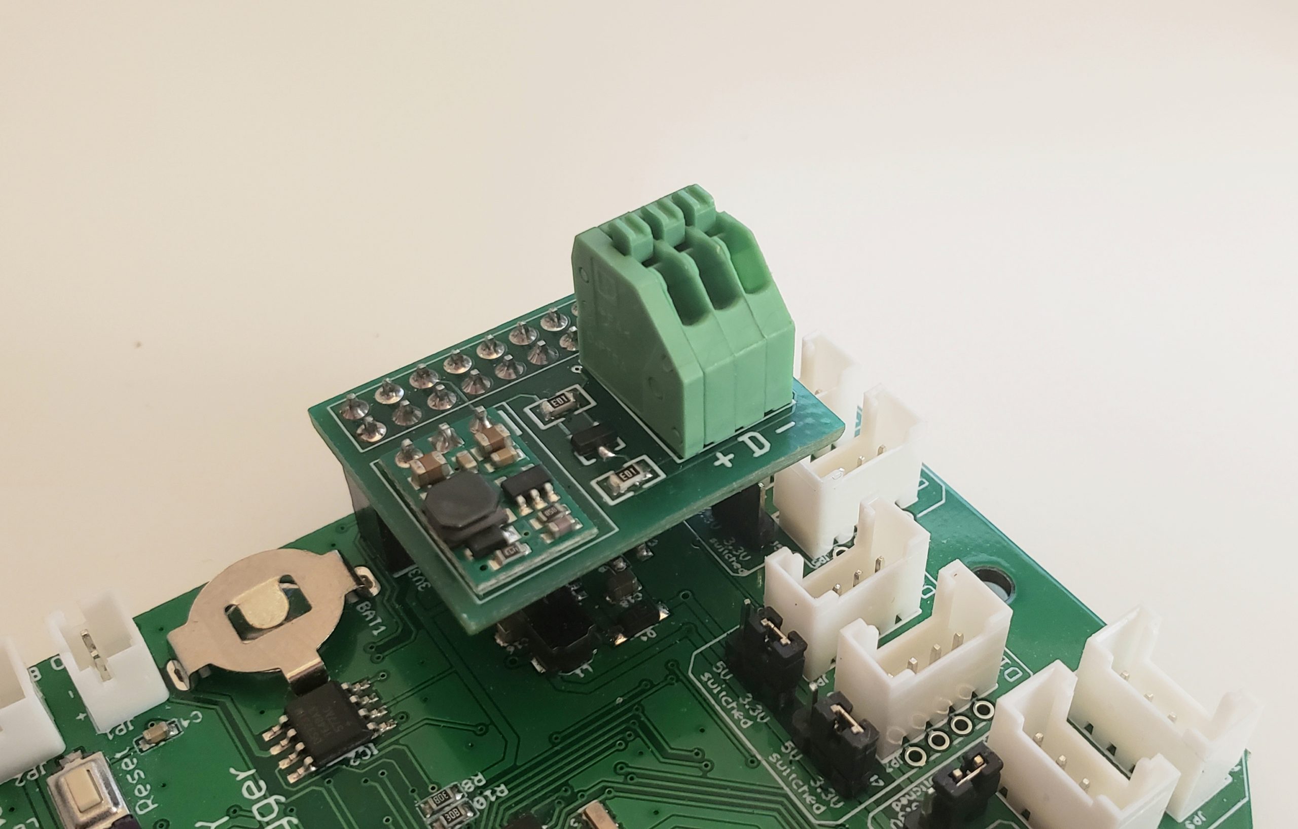
We’ve encountered a few SDI12 sensors that are more picky about the data line voltage being actually 5v instead of 3.3v, and when sensor excitation line needs 9v or 12v, then we definitely need something between the Mayfly and the sensor. I’ve hand-built a bunch of little adapter boards (see attached photo) for those sensors, using a BSS138, some resistors, and a really cheap 9v or 12v step-up module from Pololu. This seems to work for every sensor we’ve tried it on, but it’s not ideal. I’m working on an even better SDI12 level shifting module using a different technique, but I’ll write more about that in the next week or two.
Attachments:
Are you following the instructions from the top of this page to add the Mayfly board to your IDE: https://www.envirodiy.org/mayfly/software/
You should be able to copy-and-past the URL of the json file into the appropriate place in the IDE Preference window and then the IDE will fetch the file and load it properly. We haven’t made any changes to the board definition files in several years, so there shouldn’t be any problems. What version of the Arduino IDE are you using?
That panel wouldn’t be a problem. Any panel that produces 6v will be safe for the Mayfly, but some cheap 6v panels actually produce higher than 6v in direct sun, so you should measure it (under load) in full sun to make sure it won’t output higher than the max input voltage of the MCP73831 (7 volts). The solar charger on the Mayfly boards v0.5b and earlier will limit the charging current to 500ma output to the battery no matter what the solar panel power output is, so you won’t damage the battery.
Are you using Windows or Mac for connecting to the Mayfly board? Have you tried more than one USB cable? Are these two unresponsive Mayfly boards brand new or are they running previously-programmed sketches? Are there any LEDs that light up when you power the Mayfly board, either from a USB cable or a LiPo battery pack? Is the small slide switch near the FTDI connector set to the “USB/Lipo” setting and not the “Ext” setting?
Those sensors use Modbus RS485 protocol to communicate with a host device, which the Mayfly logger can’t do natively do with its current hardware, so you’ll need to add either an aftermarket RS485-to-TTL interface board, or build one like Anthony (@aufdenkampe) has done. He, and a few other people on the forum, have deployed some Yosemitech sensors for quite awhile and should be able to provide some feedback about their performance.
There’s not a direct replacement for that sensor, meaning one with the same operating specs and output. There are some alternatives, but most are significantly more expensive, or require different interface hardware (like the Yosemitech sensors), or Turner Cyclops sensors (but require user calibration). Unless you need a turbidity sensor immediately, I’d recommend waiting just a little bit longer and there will be some good sensor options unveiled soon.
Campbell Scientific discontinued the OBB3+ sensor about a year ago. They have new turbidity sensor models in development, but I’ll let them make the announcement about when it will be ready.
No, the Meter Group sensor will not work with Modular Sensors if its address is set to ‘0’. When it’s set to ‘0’, the data string is not in proper SDI12 delimeted format and Modular Sensors won’t be able to see anything. Plus, the only way to get it to take multiple readings would be to turn the sensor power off and back on each time you want to take a reading, and use a Serial parsing code to capture the data instead of Modular Sensors SDI12 libraries.
So in order to use Modular Sensors code using SDI12 commands with a Meter Group sensor, you MUST change the channel to something other than ‘0’.
-
AuthorPosts