Forum Replies Created
-
AuthorPosts
-
2019-03-26 at 8:15 PM in reply to: Attaching a Campbell Scientific OBS3+ turbidity sensor to Mayfly #12868
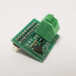
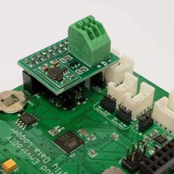
The Grove 6-pin screw terminal adapter board is now available on Amazon: https://www.amazon.com/dp/B07PVKQVH8
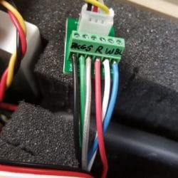
2019-03-19 at 8:15 PM in reply to: Attaching a Campbell Scientific OBS3+ turbidity sensor to Mayfly #12865The OBS sensor comes a with bare-wire cable with 6 leads. Three of them need to be connected to the Mayfly ground (sensor power ground, sensor signal ground, and sensor shield). Then the 3 other sensor wires get connected to the remaining 3 pins of a Grove terminal (note, you have to use one of the two Aux A/D Grove inputs only). Seeedstudio make a 4-pin screw terminal Grove board, but the hard part is getting all 3 ground wires into one tiny screw terminal, so I designed the custom 6-pin screw terminal board because it has two additional ground terminals. If you didn’t want to use a screw terminal, you could just take a Grove cable, cut it in half, strip the ends, and solder them together, making sure you get the power and two analog signal wires connected to the right wires, and solder all 3 sensor ground wires to the single Grove cable ground wire. But the Grove cables have a very small gage wire in them which is hard to solder properly, and will likely break under frequent flexing unless you properly protect it. And if you do all of this cable soldering outside of the Pelican case, it’s impossible to cram the Grove connector through the cable gland in the bottom of the case.
So the easiest thing is to just run the 6 bare wires into the bottom of the Pelican case and use the 6-pin screw terminal. If you can wait about a week, they’ll be available in the Amazon store for purchase.
Attachments:
2019-03-19 at 12:16 PM in reply to: Attaching a Campbell Scientific OBS3+ turbidity sensor to Mayfly #12862We currently don’t sell the screw terminal adapter, but I’m working on getting them to Amazon this week. I’ll post an update here when they are available.
The Mayfly can handle up to 16v input without risk of blowing anything up. I designed it that way so people can power it with a 12v battery that’s also attached to a charger, so their battery sees up to 15v sometimes, but still won’t hurt the Mayfly.
The cable I usually use for the ultrasonic sensors is this McMaster-Carr part number: 8233T32
It’s a CMR rated 4-conductor, stranded, shielded, 22ga cable. It also happens to have a CMX rating which makes it sunlight resistant and suitable for outdoor and wet locations. Most other mult-conductor cables (like the kind you can find at the local hardware stores) are not suitable for wet locations or will break down in sunlight, so the jacket will absorb water over time or will crack and degrade due to UV light exposure.
Yes, that cable option should be fine. I’ve made my own waterproof housing for the sensor end using a threaded PVC coupler and a cable gland since that’s cheaper. You won’t need a 6-pin screw terminal since there’s only 3 wires to connect (power, ground, and data). You can connect a 4th line to the start/stop pin of the sensor if you want to trigger the readings that way, but it’s not necessary. So just a regular Grove-to-4-terminal board would work fine for connecting it to one of the Mayfly’s Grove ports.
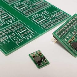
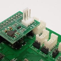
2019-02-22 at 11:44 AM in reply to: Campbell Scientific CS-215 SDI-12 communication issues w/ Mayfly #12811I had one project recently that required more than 30 Mayfly boards where each would interface with one SDI-12 soil moisture sensor array that requires 9v excitation. So I drew up this little custom PCB (not in Eagle), had it printed, and assembled the boards myself. It’s essentially one channel of the Sparkfun level converter board mentioned above, using a BSS138 MOSFET and two resistors. I also added a spot for a 9v boost converter board (https://www.pololu.com/product/2116) which also comes in 5v and 12v versions. It requires cutting the boards apart on a band saw, and then the hardest part is hand-assembling the 3 SMD parts, but if you’ve got a steady hand and a hot-air rework station or oven, it’s easy. I used a 3-position spring-latch terminal block, but you could use screw terminals or Molex pins as shown in the other photos.
For those interested in the Eagle files for the full Mayfly board, we have released the Eagle .brd and .sch files for the latest Mayfly v0.5b board.
https://github.com/EnviroDIY/EnviroDIY_Mayfly_Logger/tree/master/hardware2019-02-18 at 5:49 PM in reply to: Campbell Scientific CS-215 SDI-12 communication issues w/ Mayfly #12802We’ve used a Mayfly successfully with a variety of SDI-12 sensors from different manufacturers, including ones that require 9v or 12v excitation. I usually use a custom simple logic level converter with most of them, similar to the Sparkfun item Greg mentioned above. However the only ones that gave us problems were the YSI 6-series sondes, so I don’t have any tips for working with those.
It might be an error in how the file was downloaded from Github. Try downloading this zip file that contains both the sch and brd file. Click on the gray “Download” button on the top right to download the zip file.
https://github.com/EnviroDIY/EnviroDIY_Mayfly_Logger/blob/master/hardware/protoshield/protoshield_mayfly_v1_zip.zip -
AuthorPosts

 Welcome to EnviroDIY, a community for do-it-yourself environmental science and monitoring. EnviroDIY is part of