Forum Replies Created
-
AuthorPosts
-
Here’s the code running on the UnoEthernet/Xbee shown above, but with the URL and IP addresses removed. I based this all from some examples I found about 6 years ago, so there’s probably better ways to do this nowadays.
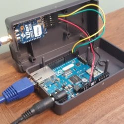
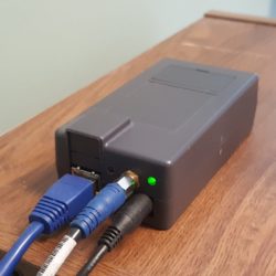
Arduino123456789101112131415161718192021222324252627282930313233343536373839404142434445464748495051525354555657585960616263646566676869707172737475767778798081828384858687888990919293949596979899100101102103104105/*Feb 18, 2013With Xbee radio attached to pins 2 and 3, and ethernet shield connected to Arduino (or use Uno Ethernet),this sketch takes any captured string and sends it to a URL of a server running a php scriptthat captures the data and writes it to a mySQL database*/#include <SPI.h>#include <Ethernet.h>#include <SoftwareSerial.h>SoftwareSerial xbeeSerial(2, 3); // RX, TXString readString = ""; //temporary string to store the incoming xbee databoolean stringComplete = false; // whether the string is completebyte mac[] = { 0x22, 0x22, 0x55, 0x55, 0x99, 0x99 }; // put the unique MAC address of your Uno ethernet board hereIPAddress server(192, 555, 999, 999); // IP address of the name server for where your php script residesEthernetClient client;void setup() {// start serial port:Serial.begin(57600);xbeeSerial.begin(2400); //The Xbee 900mhz module has trouble capturing faster than 2400baud with the UnoEthernet//so be sure to program the Xbee module's baud rate beforehand using XCTUSerial.println("sends entire captured string (with full url) to whatever URL is captured");Serial.println("Also resests the ethernet connection if it gets disconnected at some point");// start the Ethernet connection:if (Ethernet.begin(mac) == 0) {Serial.println("Failed to configure Ethernet using DHCP");// DHCP failed, so use a fixed IP address:}}void loop() // run over and over{//delay(100);if (stringComplete) {Serial.print("CapturedString: ");Serial.print(readString);//delay(1000);sendData(readString); //goes to URL and posts the data// clear the string:Serial.println("Clearing string...");readString = "";stringComplete = false;}if (xbeeSerial.available() >0) {char c = xbeeSerial.read(); //gets one byte from serial buffer//if((c>='0' and c<='9') || c==' ')//{//Serial.print(c);readString += c; //makes the string readString//}if (c == '\n') {stringComplete = true; }//Serial.write(xbeeSerial.read()); prints each character if you really want to see each one as it comes in}}void sendData(String thisData) {// if there's a successful connection:Serial.println("connecting to server...");if (client.connect(server, 80)) {Serial.println("connected");// Make a HTTP request:client.print("GET http://www.somewebsite.com/demo.php?"); //place your complete URL address hereclient.println(thisData);client.println(" HTTP/1.0");client.println("Host: http://www.somewebsite.com");client.println();client.stop();Serial.println("Data sent to the website");delay(100);}else {Serial.println("internet connection failed");delay(1000);//reset the Arduino module to hopefully fix the dropped internet connectionclient.stop();delay(1000);Ethernet.begin(mac);delay(1000);}} //end sendDataHere’s a couple photos of the UnoEthernet/Xbee receiver I built a long time ago. I has been running non-stop since February 2013 and receives about 4500 transmissions per day. With an average of 10 parameters per transmission, that’s 16.5 million parameters per year, so this little box has passed over 80 million parameters into my simple database in the past 5 years. I haven’t had to restart it do anything in the past 5 years except once when I had to update the IP address of the destination website nameserver when the host did some updates that resulted in a new address.
The Xbee module is a XbeePro 900Mhz and is mounted to an Xbee adapter board from Adafruit. I drilled holes in the case and bent the LEDs so that they poke through the case you can see the Xbee’s status. It’s held on to the case by the SMA jack of the XbeePro. It’s connected to a coax line that runs to the roof where we mounted a high-gain omnidirectional antenna.
This is what we use for receiving data from all of the stations within about a mile of our research lab. The rest of our dataloggers in other locations send data to the database via cellular modules with a $5/month cell plan from Hologram.io
We have more than 100 loggers streaming live data every 5 minutes, that adds up to around 9 million points per month and over 100 million points per year.
Attachments:
The Mayfly has an ADS1115 16-bit A/D converter on it. To use it, you can use the Adafruit ADS1x15 library and follow the tutorial on this page: https://learn.adafruit.com/adafruit-4-channel-adc-breakouts?view=all
The library comes with examples for single-ended and differential measurements. So you can follow the differential example to take a reading with the Mayfly. The ADS1115 on the Mayfly is at the default I2C address of 0x48. Using the default gain of 2/3, you’ll have a resolution of 0.1875mV per bit. So if you want 0.1mV resolution, you need to switch the gain to 2 so you’ll get 0.0625mV per bit. But that also limits the range of the maximum input voltage, so be careful not to exceed it. Exact details about the resolution and gain settings can be found in the example sketch that comes with the library.
I don’t know of anyone who has used that particular sensor with a Mayfly, but it could be theoretically possible. That sensor works by sending it an excitation voltage and then measuring the differential voltage it returns. The Mayfly has an auxiliary A/D converter that allows you to do differential measurements. You’d also have to buy the A547 interface adapter since the sensor doesn’t connect directly to the logger. One issue is that the sensor is designed to use an AC excitation instead of DC, so it might not perform properly with a DC excitation. You could add some more circuitry and get fancy with your code if you wanted to generate an AC signal with the Mayfly, but that’s not going to be easy. And then there’s all the calibration equations needed to take the measured voltages from the conductivity sensor and the thermistor to turn them into actual units of EC and temperature. There’s some info and example CRBasic code in the manual if you want to try adapting that to Arduino code. Otherwise, I think the easier option would be to use a a different conductivity sensor that has an easier output like serial or SDI-12.
The easiest way build a base station for relaying data heard via Xbee is to use an Uno Ethernet board (it’s like an Uno but has built-in ethernet hardware, so no separate shield is needed). Then connect the Xbee to the Uno Ethernet and write a script to capture all the incoming Xbee data and send it to the appropriate web site URL. I built several systems like this over the past few years, and they work non-stop relaying several thousand transmissions each day. I’ll post a picture of the boards and the little enclosure I put them in, but it’s all relatively simple and around $100.
If your logger location has Wifi, you could also just use a Wifi-bee module and send data directly to the web from the Mayfly. Or use a GPRSbee to send it via cellular.
As for the database, if you don’t have experience with SQL and HTML, it’s not simple to set up all the database stuff and the supporting web host and pages. That’s how I did it for the past 5 years with our original system, and it’s probably too complicated for most users. But we’ve been developing a new system at http://data.envirodiy.org where users can send their data to the site where it can be stored and can easily be seen with a time series viewer. We’re working on the documentation on how to write the Arduino code for how to send data to the site, but there should be some examples in our Github repository to get you started.
Xbee modules plugged in to the Mayfly’s Bee headers communicate directly with the ATmega1284P processor’s secondary hardware serial port. So if you want to see any Bee traffic on your serial monitor, you’ll need to have a sketch running on the Mayfly that captures anything heard on “Serial1” and then print it to the monitor via Serial.
Likewise, if you want the Mayfly to transmit something via the Bee, you have to do that via “Serial1”.
I got that connector from All Electronics: https://www.allelectronics.com/item/con-242/2-pin-connector-w/header-.10/1.html
Any 2-pin header with standard 0.1″ (2.5mm) spacing will work, though I prefer the ones from AllElectronics because they’re polarized and come with the prewired matching cable with 8″ leads. They’re made specifically for that company, so you can’t find them elsewhere.
Otherwise, you can use a basic Molex 2-pin polarized header, but then you’ll also need the mating jack and crimp pins.
This wouldn’t be possible using the built-in solar chargers on the Mayfly board. But it would be possible to have one separate main 6v-12v battery and solar panel (with appropriate external solar charge controller), and then you could just connect both Mayfly boards to that one battery via the Mayfly’s “External 4-12v” jack. Something like a 6v SLA battery with a small panel and controller would be pretty cheap and would have plenty of capacity to power two (or more) Mayfly boards.
We just received a big shipment of new Mayfly boards from the manufacturer yesterday, I tested a bunch today and boxed them up, so they’ll be on their way to Amazon tomorrow. You should see the boards available on Amazon next week sometime, with the kits available the week after that. We had a lot of orders right before the holidays that drained our Amazon stock, so we didn’t know they’d all sell out so quickly.
After a Mayfly workshop earlier this week, I helped 2 people install the IDE and Mayfly drivers on their Macs, using the latest Arduino IDE and by following the directions on this site, and it went smoothly with no issues. Are you just not seeing the EnviroDIY boards listed when you choose “Contributed”? If you’ve pasted the URL properly into the box on the IDE your preference tab, it should work.
-
AuthorPosts

 Welcome to EnviroDIY, a community for do-it-yourself environmental science and monitoring. EnviroDIY is part of
