Forum Replies Created
-
AuthorPosts
-
In asking about “your other thread” I meant this: https://www.envirodiy.org/topic/sd-card-recording-data-issue/
You need to make the modifications I mentioned above. You also need to pick a file name that is less than 8 characters, ie, “cond.txt” instead of conductivity.txt. I’d forgotten about the filename issue.
Your new code would be:
C++123456789101112131415161718192021222324252627282930313233343536373839404142434445464748495051#include <Arduino.h>#include <math.h>#include <Wire.h>#include <SD.h>#include <SPI.h>//Digital pin 12 is the MicroSD slave select pin on the Mayfly#define SD_SS_PIN 12//The data log file#define FILE_NAME "Conductivity.txt"//Data header (these lines get written to the beginning of a file when it’s created)#define LOGGERNAME "Mayfly microSD Card Tester"#define DATA_HEADER "Conductivity.txt"int pin12 = 12;File Conductivity1;int volta;float Division;void setup(){Serial.begin(9600);pinMode(SD_SS_PIN,OUTPUT);pinMode(22,OUTPUT);digitalWrite(22,HIGH);Division = 0.0048875;if (SD.begin(SD_SS_PIN)){Serial.println("SD card on");}else{Serial.println("SD card activation failed");}}void loop(){volta = analogRead(A3);float voltage = (volta)*(Division);Conductivity1 = SD.open("Conducti.txt",FILE_WRITE); // NOTE: REMOVE "File" and choose a file name that is 8 characters or lessSerial.println("Conductivity = ");Serial.println(voltage);Conductivity1.println(LOGGERNAME);Conductivity1.println("Conductivity = ");Conductivity1.println(voltage);Conductivity1.close(); // NOTE: Must close file or data will not be saveddelay (1000);}I still recommend you use SdFat instead of SD, which would allow you to use longer filenames and to set the file timestamps. Look at the example for that library: https://github.com/greiman/SdFat/blob/master/examples/ReadWrite/ReadWrite.ino
Did you get a chance to do any more troubleshooting on this?
It sounds like what you’re really after is a good LIMS system to help your technicians ties measurements to the correct sites and then visualize them all together on a map. The MontitorMW portal can only really help with the visualization part.
Yay! That’s more like it.
There are several posts and GitHub issues comparing the two but here’s a quick summary:
Bypass:
+ connects to the network faster
+ near 100% success in sending data if a network connection is made
– every transmission uses very slightly more data (in uncontrollable overhead – unsure why)
– Digi strongly discourages use of bypass
– rarely freezes logger to the point of a watch dog reset (cause unknown)Transparent:
+ recommended by Digi
+ uses very slightly less data
– takes longer to connect
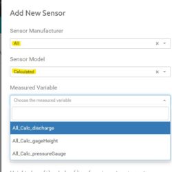
– occasional empty sessions where the internet connection is made but data isn’t successfully transferred (suspect a problem within the Digi firmware in packeting the data)Select “All” as the manufacturer and “Calculated” as the sensor model.
Attachments:
Oops. So, it never tried for longer than 15 minutes with that sketch because the watchdog doesn’t get “fed” while it’s waiting for the internet and it “bites” (ie, forces the board to reset) after 15 minutes. But 15 minutes is still a pretty long time to wait.
After the first connection in a new location, it should connect much faster in subsequent attempts. That is, if you can convince it to connect at all. From your log it doesn’t look like there’s anything wrong with the board programming; the XBee is just really, really convinced that it cannot connect to the network. Can you go back and try bypass mode again with both the USB *and* the LiPo plugged in and post that log? The trick that @neilh20 recommended is basically to send the XBee the command you would have used if you were in bypass mode but without actually entering bypass. Of course, based on all the manuals, that *shouldn’t* work, but if it’s stupid and it works…
To connect the XBee3 with XCTU you do need another adapter or development board. The XBee3 TH development board is probably the easiest way to connect them (https://www.digi.com/products/models/xbib-cu-th) because it uses USB-C to provide enough power and also separately breaks out the USB direct pins for easy plugging in straight to the SARA module. If you’re going to be using a bunch of XBee3’s, just spend the $70 and make your life a lot easier. If this is a one-off, I think there are ways to update “over the air” but it’s not as easy. To just check your firmware version you can run something like this on the Mayfly:
C++123456789101112131415161718192021222324252627282930313233343536373839404142434445#include <StreamDebugger.h>void setup() {// Set console baud rateSerial.begin(115200);delay(10);// Set XBee module baud rateSerial1.begin(9600);// Get into command modedelay(1500);Serial.println('+++');Serial1.print('+++');while (!Serial1.available()){}while (Serial1.available()) {Serial.print(Serial1.read());}Serial.println();// Sometimes it "forgets" to answer requests for versions, so we'll try 5 timesfor (uint8_t i = 0; i < 5; i++) {// Get the Digi firmware versionSerial.println('ATVR');Serial1.println('ATVR');while (!Serial1.available()){}while (Serial1.available()) {Serial.print(Serial1.read());}Serial.println();// Get the u-blox firmware versionSerial.println('ATMV');Serial1.println('ATMV');while (!Serial1.available()){}while (Serial1.available()) {Serial.print(Serial1.read());}Serial.println();}}void loop() {}Hm. I’m not quite sure I follow you.
It sounds like you have a sensor package that you deploy at one spot for a while, then you stop it, pack it up, and move it somewhere else. After some time, you move the sensor package back to the original site. Is there ever data being collected while it’s moving, or is the GPS data only being collected to help the technician remember where they were on any given day? If the data is only being collected in discrete chunks while the sensors are stationary, you could create multiple stations for each stopping point and then manually chop your data up by location and upload the chunks. It’s kind-of a pain in the bottom, but if the stations are unrelated except for the equipment you’re using to make the measurements, I think that is the appropriate way to handle the data.
I think
C++1File Conductivity1 = SD.open(“Conductivity.txt”,FILE_WRITE);should be
C++1Conductivity1 = SD.open(“Conductivity.txt”,FILE_WRITE);You also should have a
C++1Conductivity1.close()before the last delay.
Are you using a Mayfly? Are you using the built-in microSD card slot or the vertical adapter? What output do you get?
Did you ever get your program in your earlier thread to write to the SD card?
@ensign – yup, it’s a nice video. But… creating a video like that automatically for every set of uploaded trajectory data is just a little bit more difficult than making a simple plot with time on the x axis.
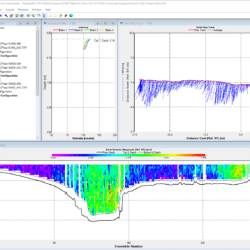
The WinRiverII software for the moving acoustic Doppler current profilers that we use to take discharge measurements has some nice visualizations for the boat tracks and the velocity profile. I think the “stick ship track” plot is a really nice way of cramming multi-dimensional data into a very simple single plot. But even though it’s “trajectory” data, the path of the ADCP is much simpler than what I’m guessing @osca is up to and MonitorMW still couldn’t handle it.
Attachments:
Hm. You have the LiPo plugged in in addition to the USB, right?
Are you sure you have service and the antenna is well connected? Don’t yank the antenna off unless you really have to; those u.Fl connectors are fragile and after 3 or 4 times of being disconnected and reconnected they stop working.
Have you ever gotten your XBee3 to connect? Sometimes it needs a long time on before it will make the first connection (think 20+ minutes). The sketch only waits two minutes on boot up and ~45 seconds every data point there-after. You can make it wait longer by changing the time in line 302 “if (modem.connectInternet(120000L)).” 120,000 ms = 2 minutes
Did you try changing from Transparent to Bypass mode? The instructions are in the thread you linked earlier. Sometimes that’s a magical fix for connection issues.
Can you connect the XBee3 directly to a computer and talk to it with XCTU? Do you have the latest firmware on the XBee3 and the SARA-R410M? If you’ve bought it within the last few months, it probably has at least the most crucial firmware updates, but the very latest is best, if possible.
Can you post a log from the same sketch, but change your settings in the terminal to use CR as the end-of-line. In transparent mode the XBee3 uses CR instead of the more typical CR+LF so you need to change the line endings to see all back and forth communication. In PlatformIO on Atom, you can select the line ending by expanding the extra options in the pop-up window when you open the serial port monitor. If you’re using PlatformIO on VSCode, you need to add these lines to your platformio.ini file in the env section:
INI123monitor_flags =--eolCRIt’s funny.. @ensign and I were on a call the other day with someone who had just started working with a different SARA R410M board and was praising the chip’s reliability. My response was “if you haven’t seen any issues with it yet, it’s because you haven’t used it enough.”
-
AuthorPosts

 Welcome to EnviroDIY, a community for do-it-yourself environmental science and monitoring. EnviroDIY is part of
