Forum Replies Created
-
AuthorPosts
-
Hi Neilh,
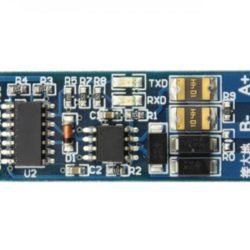
I had successfully read LT400 through Modbus potocol. The TTL to RS485 coverter I was use showed in the attached photo.
I am using an external 12V battery for the testing setup.
I burnt out one of the logic pin somehow, I could not find out the reason. maybe the 12V meet the logic pin accidentally.
I sent a private message to you with the link to download my LT400 Modbus test programme, hope that it can help you.
My 3G datalogger read LT400 through SDI12. I directly connect 3.7 Li battery to the LT400 power. It worked very well so far.
I remember I tried once connect 3.7 Li battery to LT400 and read it through Modbus. It worked, but I am not testing it hardly so I am not sure of it.
So far my SDI12 datalogger working well and I am not putting time modify it to Modbus.(I am now trying to read Soil Instrument TLT6 MEMS tilt sensor by Mayfly datalogger)
Attachments:
2017-12-28 at 12:59 AM in reply to: Looking for a bare-bones 16 bit 0-5V dc data logger sketch to build off of #2467Hi
I designed my datalogger using Mayfly with a 4000mAh 3.7 Li battery and a 0.75W 6V solar panel.
Sleep mode was added.
The battery can last for 30 days (4.13V drop to 3.7V) without solar panel. If solar panel added, It can provide enough power even during cloudy day.10W solar panel may be too much. But it is really depend on the power consumption of your system and the solar radiation shined on your system.
The mayfly lipo charger MCP73831 only accept input voltage from 3.75V to 6V. You cant connect a 12V solar panel to it.
If you want to do it, I suggest you connect the solar panel to a solar controller(charging a battery) and the 12V output connect to the external 4-12V input of Mayfly.
The mayfly lipo charger MCP73831 only accept input voltage from 3.75V to 6V. You cant connect a 12V solar panel to it.
If you want to do it, I suggest you connect the solar panel to a solar controller(charging a battery) and the 12V output connect to the external 4-12V input of Mayfly.
I dont suggest you to connect the solar panel to Mayfly and battery directly.
I tested the SDI12_Mod.h solely and the microcontroller will restart after begin the library 🙁
Problem solved(7 Feb 2017)
I am now using hardware interrupts D10 (you need to cut the trace solder a jumper to D10 at SJ1 on the back of the board)
Now you don’t need the pin change interrupt library(conflict with SDI library)Below is the code:
12345678910111213141516171819202122232425262728293031323334353637383940414243444546474849505152535455565758596061626364656667686970717273//Sleep mode setting#include <avr/sleep.h>//RTC Setting#include <Wire.h>#include <Sodaq_DS3231.h>char time_stamp[20];void setup(){//Start SerialSerial.begin(57600);//Begin RTCSerial.println("Begin RTC");if (!rtc.begin()){Serial.println("Couldn't find RTC");}//rtc.setDateTime(DateTime(__DATE__, __TIME__));//Begin sleep modepinMode(10, INPUT_PULLUP);attachInterrupt(2, wakeISR, FALLING);rtc.enableInterrupts(EveryMinute); //RTC interrupt modeset_sleep_mode(SLEEP_MODE_PWR_DOWN); //Set the sleep modeSerial.println("Setup completed!!!");}void loop(){Serial.print("logging at: ");sprintf(time_stamp, "%02d:%02d:%02d",rtc.now().hour(),rtc.now().minute(),rtc.now().second());Serial.println(time_stamp);//delay(10000);//SleepsystemSleep();}void wakeISR(){//Leave this blank}void systemSleep(){//Wait until the serial ports have finished transmittingSerial.flush();//Serial1.flush();//The next timed interrupt will not be sent until this is clearedrtc.clearINTStatus();//Disable ADCADCSRA &= ~_BV(ADEN);//Sleep timenoInterrupts();sleep_enable();interrupts();sleep_cpu();//wake up heresleep_disable();//Enbale ADCADCSRA |= _BV(ADEN);}Thx Shannon!
I will test it in coming days.
Hi Shannon.
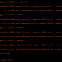
I try to combine the sleep mode code to my SDI12 logger code. Unfortunately the SDI12 library crash with the Sodaq PcInt library.
I am not familiar with how Arduino library work. Is that any way can solve it? So that I can implement the sleep mode in my SDI12 logger
Below is the Error:
Attachments:
I am using Level Troll 400 .
For the current setup(using Mayfly datalogger) with cable length 1 m to sensor, I only test it in office for four days.
Previous setup(replaced by Mayfly now) using Pro Micro, SD breakout, RTC breakout and 3G breakout. I tested it in office for 21 days.Both test result were good. But still need to fix some minor problems
I will put it to site for testing in coming few days
Thanks for the user friendly spacing! I didn’t get any trouble.
I am using In-situ Inc Level TROLL Data Logger for water level monitoring.
https://in-situ.com/product-category/water-level-monitoring/
The extra pins are for RS485(2 pins) and 4-20mA(1 pin). I am not using it now but I may switch from SDI12 to RS485 in future.I may purchase more Mayfly data logger in future. The microSD vertical adapter is necessary in my design because my logger enclosure is narrow. It is good if the microSD vertical adapter board sale separately in Amazon
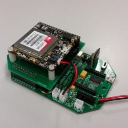
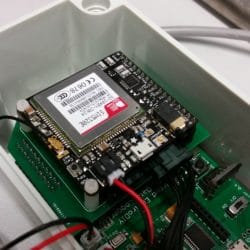
I designed a simple shield for Adafruit FONA 3G cellular breakout. The shield also include two sockets for SDI12 sensor
-
AuthorPosts

 Welcome to EnviroDIY, a community for do-it-yourself environmental science and monitoring. EnviroDIY is part of