Home › Forums › Mayfly Data Logger › Abnormally high battery voltage
- This topic has 4 replies, 4 voices, and was last updated 2022-05-02 at 8:32 PM by
 neilh20.
-
AuthorPosts
-
-
2022-04-29 at 3:43 PM #16978
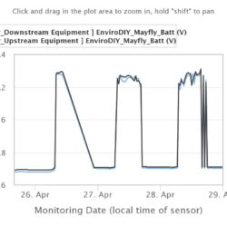
We have 2 stations we’ve recently deployed which are reporting ~7.5 volts during the day and 4.2V at night (graphs attached).
I suspect that the solar cable was accidentally plugged into one of the LIPO BATT ports (with the battery plugged into the other LIPO BATT port). They’ll get that corrected asap, but I want to ask @shicks: Would this harm the Mayfly circuitry? Presumably the stations’ batteries are not being charged, but hopefully the regulator, etc., were not harmed.
The affected stations are here and here.
Configuration for each is:
- Mayfly v1.0
- 6W 6V Voltaic solar panel
- 6600 mAh LiPo
- EnviroDIY LTE modem
- Turner Turbidity Plus
- Meter Hydros-21
Attachments:
-
2022-04-29 at 4:17 PM #16980
I am curious, did this just start or when you look back on battery voltage has it been doing this foe a while ? TomG2
-
2022-04-29 at 4:25 PM #16981
These were just deployed 3 days ago and have been doing this from the beginning.
-
2022-05-02 at 10:50 AM #16983
Matt, you are correct that it appears the solar panel was connected to the spare LipoBatt JST socket on the Mayfly, which causes the board to see those high levels during the day. The voltage regulator on the Mayfly can theoretically be damaged if you put more than 6.5v into the board via the LipoBatt jack, so they should definitely fix that as soon as possible. The big question is whether this damaged the regulator on the Mayfly or the battery pack. Once the panel is back on the correct SOLAR jack, you can look at the station data after a day or two and determine if things are behaving normally or not.
For the record, the JST jacks on the Mayfly have always been a little confusing, since there are 3 of them; only one is to be used by the solar panel, and the other two are for the Lipo battery, but only one battery can be attached at a time. This is a holdover from previous Mayfly designs where accessory boards like the older cellular bees require a separate power jumper to get power directly from the Lipo. Now that we’ve got our own LTE cell boards that don’t require that jumper, we’re moving towards only having one JST jack for the Lipo and removing the JST jack for the solar panel, which is why I added the new black quick-connector on the Mayfly v1.0. But since there are so many existing stations in the field with the existing configurations for solar and cellular, I didn’t want to totally remove those extra JST sockets on the Mayfly just yet.
If you’d like to prevent future people from accidentally connecting the solar panel to the spare Lipo jack, I’d suggest cutting one of the Lipo jacks off. To do this, make sure the Mayfly is completely unpowered with nothing connected (no solar, no battery, no USB). Use needle-nose pliers to pull up on the plastic housing of one of the JST jacks and it’ll pop off pretty easily. Now use a small pair of diagonal cutters to snip off the 2 pins flush with the circuit board. Now you’ve only got one Lipo jack on the Mayfly, and if you really want to prevent errors, remove the SOLAR JST jack from your Mayfly using the same technique, then cut off the JST plug from the solar panel wire and use the black quick-connect socket instead. One is included with all Monitoring Station Kits sold in the EnviroDIY shop, otherwise they can be purchased separately from places like Digikey: https://www.digikey.com/en/products/detail/phoenix-contact/1778832/2625556
-
2022-05-02 at 8:32 PM #16989
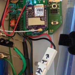
For the solar connecter, I colour the socket and the jack in an acrylic orange so that there is a visual match. The LiIon battery in a cooler blue. Of course have to be careful to only get the acrylic paint on the outside of the jack and not have leak inside. Its not perfect, but provides a little clue.
Attachments:
-
-
AuthorPosts
- You must be logged in to reply to this topic.

 Welcome to EnviroDIY, a community for do-it-yourself environmental science and monitoring. EnviroDIY is part of
