Home › Forums › Mayfly Data Logger › Can't read/store values from Yosemitech using WingShield
Tagged: AltSoftSerial, modbus, SoftwareSerial, wingshield, yosemitech
- This topic has 5 replies, 4 voices, and was last updated 2019-10-24 at 2:49 PM by
 Sara Damiano.
-
AuthorPosts
-
-
2019-09-17 at 2:20 AM #13149
Hello and greetings from New Zealand,
My work group is developing some mayfly loggers and we have run into a problem using Modbus with a Yosemitech Y4000 sensor, measuring pH, conductivity, temperature, turbidity, and dissolved oxygen. We are attempting to communicate to this device using the WingShield and Modbus (as described on the EnviroDIY github) on the Mayfly. We have were able to successfully read data off of this unit for a while, but then, seemingly with no changes made to the code, we started getting a reading of -9999.00 for all of the sensors.
With additional fiddling, the problem got worse, and now it seems that when the mayfly tries to read and log the sample, the program just restarts from the beginning.
We are able to connect and read values off of the sensors using the GetValues.ino script in the YosemitechModbus library. However when we try to run a logging script based on the ModularSensors library, everything falls apart. I think it has to be a library issue, where my code just isn’t playing nice with one of the libraries in the EnviroDIY universe. I am using platformio with the libraries included in the ‘libraries’ enviroDIY repository.
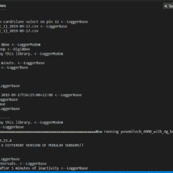
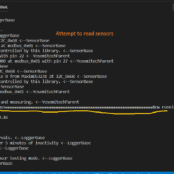
I will test it again soon and collect additional debugging info, but I thought I would just post about it now in case anyone has been having similar issues lately. Attached is a screen shot of what happens when the logger tries to save the data, and here is a recent iteration of the code I am trying to use:
123456789101112131415161718192021222324252627282930313233343536373839404142434445464748495051525354555657585960616263646566676869707172737475767778798081828384858687888990919293949596979899100101102103104105106107108109110111112113114115116117118119120121122123124125126127128129130131132133134135136137138139140141142143144145146147148149150151152153154155156157158159160161162163164165166167168169170171172173174175176177178179180181182183184185186187188189190191192193194195196197198199200201202203204205206207208209210211212213214215216217218219220221222223224225226227228229230231232233234235236237238239240241242243244245246247248249250251252253254255256257258259260261262263264265266267268269270271272273274275276277278279280281282283284285286287288289290291292293294295296297298299300301302303304305306307308309310311312313314315316317318319320321322323324325326327328329330331332333334335336337338339340341342343344345346347348349350351352353354355356357358359360361362363364365366367368369370371372373374375376377378379380381382383384385386387388389390391392393394395396397398399400401402403404405406407408409410411412413414415416417418419420421422423424// ==========================================================================// Include the base required libraries// ==========================================================================#include <Arduino.h> // The base Arduino library#include <EnableInterrupt.h> // for external and pin change interrupts#include <LoggerBase.h> // The modular sensors library// ==========================================================================// Data Logger Settings// ==========================================================================// The library version this example was written forconst char *libraryVersion = "0.23.10";// The name of this fileconst char *sketchName = "logging_to_MMW_test.ino";// Logger ID, also becomes the prefix for the name of the data file on SD cardconst char *LoggerID = "IOWtest";// How frequently (in minutes) to log dataconst uint8_t loggingInterval = 5; // set to 15 minutes -rm// Your logger's timezone.const int8_t timeZone = 12; // Eastern Standard Time// NOTE: Daylight savings time will not be applied! Please use standard time!float minimum_bat_voltage = 10.5; // defining minimum and moderate battery voltagesfloat moderate_bat_voltage = 11.5; // -rm// ==========================================================================// Primary Arduino-Based Board and Processor// ==========================================================================#include <sensors/ProcessorStats.h>const long serialBaud = 115200; // Baud rate for the primary serial port for debuggingconst int8_t greenLED = 8; // MCU pin for the green LED (-1 if not applicable)const int8_t redLED = 9; // MCU pin for the red LED (-1 if not applicable)const int8_t buttonPin = 21; // MCU pin for a button to use to enter debugging mode (-1 if not applicable)const int8_t wakePin = A7; // MCU interrupt/alarm pin to wake from sleep// Set the wake pin to -1 if you do not want the main processor to sleep.// In a SAMD system where you are using the built-in rtc, set wakePin to 1const int8_t sdCardPwrPin = -1; // MCU SD card power pin (-1 if not applicable)const int8_t sdCardSSPin = 12; // MCU SD card chip select/slave select pin (must be given!)const int8_t sensorPowerPin = 22; // MCU pin controlling main sensor power (-1 if not applicable)// Create the main processor chip "sensor" - for general metadataconst char *mcuBoardVersion = "v0.5b";ProcessorStats mcuBoard(mcuBoardVersion);// ==========================================================================// Wifi/Cellular Modem Settings// ==========================================================================// Create a reference to the serial port for the modem// Extra hardware and software serial ports are created in the "Settings for Additional Serial Ports" sectionHardwareSerial &modemSerial = Serial1; // Use hardware serial if possible// AltSoftSerial &modemSerial = altSoftSerial; // For software serial if needed// NeoSWSerial &modemSerial = neoSSerial1; // For software serial if needed// Modem Pins - Describe the physical pin connection of your modem to your board// DFRobot ESP8266 Bee with Mayflyconst int8_t modemVccPin = -1; // MCU pin controlling modem power (-1 if not applicable)const int8_t modemStatusPin = -1; // MCU pin used to read modem status (-1 if not applicable)const int8_t modemResetPin = -1; // MCU pin connected to modem reset pin (-1 if unconnected)const int8_t modemSleepRqPin = -1; // MCU pin used for wake from light sleep (-1 if not applicable)const int8_t modemLEDPin = redLED; // MCU pin connected an LED to show modem status (-1 if unconnected)// Network connection informationconst char *wifiId = "HUAWEI-2A09"; // The WiFi access point, unnecessary for gprsconst char *wifiPwd = "R09168991R4"; // The password for connecting to WiFi, unnecessary for gprs// ==========================================================================// The modem object// Note: Don't use more than one!// ==========================================================================// For almost anything based on the Espressif ESP8266 using the AT command firmware#include <modems/EspressifESP8266.h>const long modemBaud = 9600; // Communication speed of the modem// NOTE: This baud rate too fast for an 8MHz board, like the Mayfly! The module// should be programmed to a slower baud rate or set to auto-baud using the// AT+UART_CUR or AT+UART_DEF command *before* attempting control with this library.// Pins for light sleep on the ESP8266.// For power savings, I recommend NOT using these if it's possible to use deep sleep.const int8_t espSleepRqPin = -1; // GPIO# ON THE ESP8266 to assign for light sleep request (-1 if not applicable)const int8_t espStatusPin = -1; // GPIO# ON THE ESP8266 to assign for light sleep status (-1 if not applicable)EspressifESP8266 modemESP(&modemSerial,modemVccPin, modemStatusPin,modemResetPin, modemSleepRqPin,wifiId, wifiPwd,1, // measurements to average, optionalespSleepRqPin, espStatusPin // Optional arguments);// Create an extra reference to the modem by a generic name (not necessary)EspressifESP8266 modem = modemESP;#include <sensors/MaximDS3231.h>// Create a DS3231 sensor objectMaximDS3231 ds3231(1);// ==========================================================================// Decagon CTD Conductivity, Temperature, and Depth Sensor// ==========================================================================#include <sensors/DecagonCTD.h>const char *CTDSDI12address = "1"; // The SDI-12 Address of the CTDconst uint8_t CTDNumberReadings = 6; // The number of readings to averageconst int8_t SDI12Power = sensorPowerPin; // Pin to switch power on and off (-1 if unconnected)const int8_t SDI12Data = 7; // The SDI12 data pin// Create a Decagon CTD sensor objectDecagonCTD ctd(*CTDSDI12address, SDI12Power, SDI12Data, CTDNumberReadings);// ==================================================================// Analog battery voltage reading -rm// ==================================================================float getBatteryVoltage(void) // setting battery voltage to 12 for now{float battery_voltage = 0 ;battery_voltage = 12.0 ; // set to 12 to keep it logging for modbus testing -rmreturn battery_voltage;}// ==========================================================================// Yosemitech Y4000 Multiparameter Sonde (DOmgL, Turbidity, Cond, pH, Temp, ORP, Chlorophyll, BGA)// ==========================================================================#include <AltSoftSerial.h>AltSoftSerial altSoftSerial;#include <sensors/YosemitechY4000.h>// Create a reference to the serial port for modbus// Extra hardware and software serial ports are created in the "Settings for Additional Serial Ports" section#if defined ARDUINO_ARCH_SAMD || defined ATMEGA2560HardwareSerial &modbusSerial = Serial2; // Use hardware serial if possible#elseAltSoftSerial &modbusSerial = altSoftSerial; // For software serial if needed// NeoSWSerial &modbusSerial = neoSSerial1; // For software serial if needed#endifbyte y4000ModbusAddress = 0x01; // The modbus address of the Y4000const int8_t rs485AdapterPower = sensorPowerPin; // Pin to switch RS485 adapter power on and off (-1 if unconnected)const int8_t modbusSensorPower = -1; // Pin to switch sensor power on and off (-1 if unconnected) //const int8_t max485EnablePin = -1; // Pin connected to the RE/DE on the 485 chip (-1 if unconnected)const uint8_t y4000NumberReadings = 5; // The manufacturer recommends averaging 10 readings, but we take 5 to minimize power consumption// Create a Yosemitech Y4000 multi-parameter sensor objectYosemitechY4000 y4000(y4000ModbusAddress, modbusSerial, rs485AdapterPower, modbusSensorPower, max485EnablePin, y4000NumberReadings);// Create all of the variable pointers for the Y4000// Variable *y4000DO = new YosemitechY4000_DOmgL(&y4000, "48589f6a-046c-48f4-84ef-3eb25ad07702")// Variable *y4000Turb = new YosemitechY4000_Turbidity(&y4000, "46daf79d-3cd6-43b2-b8b2-dbcdce1e4c1c"),// Variable *y4000Cond = new YosemitechY4000_Cond(&y4000, "2dab997c-0d38-4b0f-9116-43e27893feaf"),// Variable *y4000pH = new YosemitechY4000_pH(&y4000, "47924fae-46ad-4fc6-99c4-d5bd629f6747"),// Variable *y4000Temp = new YosemitechY4000_Temp(&y4000, "9ed4d2a1-492c-4ae4-bd69-22dcd429c526"),// Variable *y4000ORP = new YosemitechY4000_ORP(&y4000, "12345678-abcd-1234-ef00-1234567890ab");// Variable *y4000Chloro = new YosemitechY4000_Chlorophyll(&y4000, "12345678-abcd-1234-ef00-1234567890ab");// Variable *y4000BGA = new YosemitechY4000_BGA(&y4000, "12345678-abcd-1234-ef00-1234567890ab");// ==========================================================================// Creating the Variable Array[s] and Filling with Variable Objects// ==========================================================================// FORM1: Create pointers for all of the variables from the sensors,// at the same time putting them into an array// NOTE: Forms one and two can be mixedVariable *variableList[] = {new YosemitechY4000_DOmgL(&y4000, "48589f6a-046c-48f4-84ef-3eb25ad07702"),new YosemitechY4000_Turbidity(&y4000, "46daf79d-3cd6-43b2-b8b2-dbcdce1e4c1c"),new YosemitechY4000_Cond(&y4000, "2dab997c-0d38-4b0f-9116-43e27893feaf"),new YosemitechY4000_pH(&y4000, "47924fae-46ad-4fc6-99c4-d5bd629f6747"),new YosemitechY4000_Temp(&y4000, "9ed4d2a1-492c-4ae4-bd69-22dcd429c526"),// new DecagonCTD_Cond(&ctd, "6b3ef348-eb2d-4c94-8129-ee4559bb3217"),// new DecagonCTD_Temp(&ctd, "52f50dd5-b6b6-4975-ad61-55c5f864fd3e"),// new DecagonCTD_Depth(&ctd, "d3eff5f5-92fe-4316-ae0f-75de31b0ce50"),// new ProcessorStats_Battery(&mcuBoard, "8d2a269f-0bce-4faa-b79f-7a19695f5bd2"),new MaximDS3231_Temp(&ds3231, "c6bc39f6-04a1-4ba4-8f6d-10130ec291b6"),};// Count up the number of pointers in the arrayint variableCount = sizeof(variableList) / sizeof(variableList[0]);// Create the VariableArray objectVariableArray varArray(variableCount, variableList);// ==========================================================================// The Logger Object[s]// ==========================================================================// Create a new logger instanceLogger dataLogger(LoggerID, loggingInterval, &varArray);// ==========================================================================// A Publisher to Monitor My Watershed / EnviroDIY Data Sharing Portal// ==========================================================================// Device registration and sampling feature information can be obtained after// registration at https://monitormywatershed.org or https://data.envirodiy.orgconst char *registrationToken = "e2489981-e06d-471d-8b0b-74d262612fc2"; // Device registration tokenconst char *samplingFeature = "e2231892-a21b-48ab-a93c-2df3badd4bea"; // Sampling feature UUID// Create a data publisher for the EnviroDIY/WikiWatershed POST endpoint#include <publishers/EnviroDIYPublisher.h>EnviroDIYPublisher EnviroDIYPOST(dataLogger, &modem.gsmClient, registrationToken, samplingFeature);// ==========================================================================// Working Functions// ==========================================================================// Flashes the LED's on the primary boardvoid greenredflash(uint8_t numFlash = 4, uint8_t rate = 75){for (uint8_t i = 0; i < numFlash; i++) {digitalWrite(greenLED, HIGH);digitalWrite(redLED, LOW);delay(rate);digitalWrite(greenLED, LOW);digitalWrite(redLED, HIGH);delay(rate);}digitalWrite(redLED, LOW);}// Read's the battery voltage// NOTE: This will actually return the battery level from the previous update!// I don't need this because I am using an analog pin to read the voltage -rm//float getBatteryVoltage()//{// if (mcuBoard.sensorValues[0] == -9999) mcuBoard.update();// return mcuBoard.sensorValues[0];//}// ==========================================================================// Main setup function// ==========================================================================void setup(){// Wait for USB connection to be established by PC// NOTE: Only use this when debugging - if not connected to a PC, this// could prevent the script from starting#if defined SERIAL_PORT_USBVIRTUALwhile (!SERIAL_PORT_USBVIRTUAL && (millis() < 10000)){}#endif// Start the primary serial connectionSerial.begin(serialBaud);// Print a start-up note to the first serial portSerial.print(F("Now running "));Serial.print(sketchName);Serial.print(F(" on Logger "));Serial.println(LoggerID);Serial.println();Serial.print(F("Using ModularSensors Library version "));Serial.println(MODULAR_SENSORS_VERSION);if (String(MODULAR_SENSORS_VERSION) != String(libraryVersion))Serial.println(F("WARNING: THIS EXAMPLE WAS WRITTEN FOR A DIFFERENT VERSION OF MODULAR SENSORS!!"));// Allow interrupts for software serial#if defined SoftwareSerial_ExtInts_henableInterrupt(softSerialRx, SoftwareSerial_ExtInts::handle_interrupt, CHANGE);#endif// Start the serial connection with the modemmodemSerial.begin(modemBaud);// Set up pins for the LED'spinMode(greenLED, OUTPUT);digitalWrite(greenLED, LOW);pinMode(redLED, OUTPUT);digitalWrite(redLED, LOW);// Blink the LEDs to show the board is on and starting upgreenredflash();if (sensorPowerPin >= 0){pinMode(sensorPowerPin, OUTPUT);digitalWrite(sensorPowerPin, LOW);}// Set the timezones for the logger/data and the RTC// Logging in the given time zoneLogger::setLoggerTimeZone(timeZone);// It is STRONGLY RECOMMENDED that you set the RTC to be in UTC (UTC+0)Logger::setRTCTimeZone(0);// Attach the modem and information pins to the loggerdataLogger.attachModem(modem);modem.setModemLED(modemLEDPin);dataLogger.setLoggerPins(wakePin, sdCardSSPin, sdCardPwrPin, buttonPin, greenLED);// Begin the loggerdataLogger.begin();Serial.print ("current voltage = ");Serial.println (getBatteryVoltage()); // check battery voltage -rm// Note: Please change these battery voltages to match your battery// Check that the battery is OK before powering the modemif (getBatteryVoltage() > minimum_bat_voltage){modem.modemPowerUp();modem.wake();#if F_CPU == 8000000Lif (modemBaud > 57600){modemSerial.begin(115200);modem.gsmModem.sendAT(GF("+UART_DEF=9600,8,1,0,0"));modem.gsmModem.waitResponse();modemSerial.end();modemSerial.begin(9600);}#endifmodem.setup();// At very good battery voltage, or with suspicious time stamp, sync the clock// Note: Please change these battery voltages to match your batteryif (getBatteryVoltage() > moderate_bat_voltage || //changed to use new voltage input on analog 2 -rmdataLogger.getNowEpoch() < 1546300800 || /*Before 01/01/2019*/dataLogger.getNowEpoch() > 1735689600) /*After 1/1/2025*/{// Synchronize the RTC with NISTSerial.println(F("Attempting to connect to the internet and synchronize RTC with NIST"));if (modem.connectInternet(120000L)){dataLogger.setRTClock(modem.getNISTTime());}else{Serial.println(F("Could not connect to internet for clock sync."));}}}// Set up the sensors, except at lowest battery levelif (getBatteryVoltage() > minimum_bat_voltage){Serial.println(F("Setting up sensors..."));varArray.setupSensors();}// Create the log file, adding the default header to it// Do this last so we have the best chance of getting the time correct and// all sensor names correct// Writing to the SD card can be power intensive, so if we're skipping// the sensor setup we'll skip this too.if (getBatteryVoltage() > minimum_bat_voltage){Serial.println(F("Setting up file on SD card"));dataLogger.turnOnSDcard(true); // true = wait for card to settle after power updataLogger.createLogFile(true); // true = write a new headerdataLogger.turnOffSDcard(true); // true = wait for internal housekeeping after write}// Power down the modem - but only if there will be more than 15 seconds before// the first logging interval - it can take the LTE modem that long to shut downif (Logger::getNowEpoch() % (loggingInterval*60) > 15 ||Logger::getNowEpoch() % (loggingInterval*60) < 6){Serial.println(F("Putting modem to sleep"));modem.disconnectInternet();modem.modemSleepPowerDown();}else{Serial.println(F("Leaving modem on until after first measurement"));}// Call the processor sleepSerial.println(F("Putting processor to sleep"));dataLogger.systemSleep();}// ==========================================================================// Main loop function// ==========================================================================// Use this short loop for simple data logging and sending// /*void loop(){Serial.print ("current voltage = ");Serial.println (getBatteryVoltage());// Note: Please change these battery voltages to match your battery// At very low battery, just go back to sleepif (getBatteryVoltage() < minimum_bat_voltage){dataLogger.systemSleep();}// At moderate voltage, log data but don't send it over the modemelse if (getBatteryVoltage() < moderate_bat_voltage){dataLogger.logData();}// If the battery is good, send the data to the worldelse{dataLogger.logDataAndPublish();}}Attachments:
-
2019-09-17 at 10:14 AM #13151
@rachel.murray, that’s great to hear that you were able to get the YosemiTech Y4000 sonde working with our Modbus Mayfly Wing Shield and associated documentation. I developed all of that for a team at Winona State University in Minnesota, but I hadn’t been aware of anyone else trying to integrate the Y4000 with our EnviroDIY stack. So that’s satisfying to hear that you got it working, for a while.
BTW, are you working with my friend Troy Baisden?
I will say that the Y4000 sonde is the one sensor from YosemiTech that has given me headaches to get working and also to keep working. Unfortunately I haven’t kept up with documenting everything.
The first challenge with the Y4000 is that it needs a stable and consistent 12V of power with the capacity for high amperage draw during startup and when the brush is spinning. I was able to barely get it to work on the Mayfly with the Modbus Wing + two 680 uF capacitors, but only when no other sensors were attached. The system was browning out when I attached other sensors, and I’m guessing that if the radio were drawing power while the Y4000 is on that would also brown out the system.
The solution was to wire up an independent 2 Amp 12V power supply that is switched on & off by the Mayfly. While the power for the Y4000 system comes from this separate power supply, the Modbus communication still passes through the Wing Shield. None of this is publicly documented yet, but here are my notes:
Redo Y4000 line, with built-in power regulation and switching
Overview of connections
– Battery to Pololu Power Switch HP to control by Mayfly
– Pololu 12V Voltage Regulator to SondeDetails
Pololu Big Pushbutton Power Switch with Reverse Voltage Protection, HP,
Battery Side:
– Vin to battery +, This powers the system
– GND to Battery
Sonde side (via regulator)
– Vout to 12V regulator Vin
– GND to 12V regulator GND
Mayfly Control side
– CTRL to Mayfly switched power (Setting D10)
– GND to system/Mayfly groundPololu 12V Step-Up/Step-Down Voltage Regulator S18V20F12
Battery Side (via switch)
– Vin to switch Vout
– GND to switch GND
Sonde side
– Vout to Sonde red
– GND to Sonde black -
2019-09-22 at 11:09 PM #13158
Thanks for the reply,
Yes, I am working with Troy :). We have had some success with the decagon CTD, including using a wifibee and portable wifi hotspot to log data to monitormywatershed.org. It would be nice to have turbidity measurements as well, which is one reason we are interested in the Y4000 device.
In our y4000-mayfly setup, I have tried removing the wifibee modem, along with the associated code. I have also tried running with and without other sensors. We are currently testing using an external 12V power supply to power the y4000 (left on constantly for testing purposes). Regardless of the setup, the result is the same – the mayfly can’t seem to communicate with the sensor.
The mayfly reboots right after attempting to activate the brush. This makes a brownout seem like a likely problem, however connecting to an external 12V supply doesn’t seem to help. I’m wondering if there might be some sort of problem with the serial connection using Altsoftserial.
I’m going to try a few more tests and report back – are there any particularly useful debugging flags that could shed some light on the problem?
Thanks for your help,
Rachel
Attachments:
-
2019-09-23 at 10:22 AM #13163
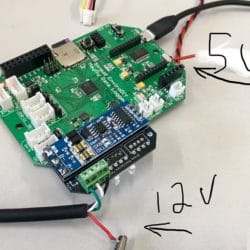
It’s hard to tell exactly what’s going on with your wires from the photo, but you should make sure your separate power supplies are sharing a common ground. If you’ve got 12v going to the sensor and 5v going to the board, you need to have the ground of both of those supplies (or batteries) connected to the same ground as the Mayfly.
-
2019-10-21 at 8:33 PM #13239
We have made sure that the power supplies are sharing the same ground. There seems to be some issue with the serial connection to the modbus, maybe related to a conflict in the libraries that handle the physical and software serial connections.
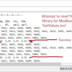
We are able to read values using SoftwareSerial as the Modbus serial connection and the ‘GetValues.ino’ script on the EnviroDIY Github (YosemitechModbus/Examples/GetValues), and we can also read values using a similar script with NeoSWSerial as the Modbus serial. However, we are unable to retrieve values using AltSoftSerial at all.
The software serial connections only work when I am running a simple test script that references the YosemitechModbus library. As soon as I try to run a logging script and reference the ModularSensors library, I can’t read any values off the Y4000, using either the modified SoftwareSerial library or NeoSWSerial. The brush is activated and then the serial output has some odd characters (sometimes it says ‘connection failed’) and then the script re-starts.
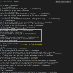
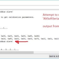
I have attached the output from the logging script, as well as the outputs from the ‘GetValues.ino’ script.
-
2019-10-24 at 2:49 PM #13247
Where is the extra red (5V?) wire in your pictures from September connected? It looks like you have the Yosemetich connected to one 12V power supply (red line at the bottom), the Mayfly powered by second 5V power supply (the black/red twisted pair?) and then the Mayfly also connected to the computer’s USB. But then I can’t figure out the extra wire. You’re sure everyone’s sharing a ground? (I know you already checked, but it’s worth checking again.)
Do you have an RS485 adapter that isn’t attached to a “WingShield” that you could test with? I don’t expect that the wing is the problem, but using the raw adapter would completely eliminate it from suspicion.
If you can use an RS485 adapter that hasn’t been built into a wing, connect it to Serial1. The hardware serial port is *always* better than any software version and using it eliminates any questions the serial libraries. We’ve had some sensors that absolutely refused to talk over anything but hardware serial.
AltSoftSerial should not (generally) conflict with much else. It uses timer capture interrupts rather than pin change interrupts that other software serial libraries use. But using too many libraries that define interrupts of any type can cause some headaches with serial communication because the timing is really important and even well written interrupt routines can throw the timing off enough to cause it to be garbled. In my experience AltSoftSerial *is* the very best alternative to hardware serial. I don’t think I ever succeed in communicating with the Yosemitech’s over the version of SoftwareSerial that’s been modified to play with the rest of ModularSensors – it’s just not accurate enough. I’m really surprised your experience has been the opposite.
Once you can get the GetValues example to run smoothly, try running modular sensors with the build flags for the variable array turned on. (MS_VARIABLEARRAY_DEBUG and MS_VARIABLEARRAY_DEBUG_DEEP) that might give me a better idea of where ModularSensors is crashing.
-
-
AuthorPosts
- You must be logged in to reply to this topic.

 Welcome to EnviroDIY, a community for do-it-yourself environmental science and monitoring. EnviroDIY is part of