Home › Forums › Mayfly Data Logger › Continous HAB monitoring
- This topic has 18 replies, 3 voices, and was last updated 2025-03-25 at 11:47 PM by
nick.
-
AuthorPosts
-
-
2024-07-05 at 5:51 PM #18562
Hi,
Has anyone setup their Mayfly data logger to monitor HABs in ponds/lakes? Right now, we are manually collecting the samples and trying to see if doing continuous monitoring would be beneficial.
Thank you.
-
2024-07-12 at 3:53 PM #18573
Yes, the Stroud Center has a Campbell Scientific phycocyanin sensor deployed on a Mayfly Data Logger. @shicks might be able to share code with you.
-
2024-07-12 at 10:31 PM #18574
They are actually Turner Designs Cyclops-7F sensors that we use for measuring chlorophyll and phycocyanin (https://www.turnerdesigns.com/cyclops-7f-submersible-fluorometer). They are supported by the ModularSensors library and there’s more information about them here: https://envirodiy.github.io/ModularSensors/group__sensor__cyclops.html
-
2024-10-29 at 3:17 PM #18711
Hi Shannon,
I ordered a C-FLOUR not realizing that the modular sensor library only has compatibility with the Cyclops-7F, even though you mentioned the Cyclops in your earlier post.
Based on what a rep has told me, Turner is starting to phase out their Cyclops-7F sensors and replacing them with the C-FLUOR sensors, since parts are getting harder to source. They said the C-FLUOR units are backwards compatible since the hardware is very similar. https://docs.turnerdesigns.com/t2/doc/comparison-guides/S-0245.pdf Based on that PDF it looks like C-FLOUR is more accurate (for Phycocyanin), faster, and calibrated.
Is there any chance the C-FLOUR can be added to the library? And possibly add an example code too?
Thank you!
-
2024-10-29 at 3:50 PM #18712
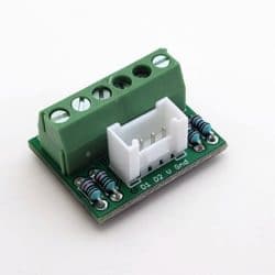
The two sensor models perform exactly the same. We’ve used a couple in the field with existing loggers when replacing some old broken Cyclops 7f sensors. All we did was swap the sensors and redo the calibration and edit the appropriate 2 lines in the code for the voltage measured in the standard and the blank (nanopure water). The C-FLUOR sensors do come with a calibration voltage on a datasheet in the package, but we prefer to do our own, plus we recalibrate them in the field periodically once deployed. We use a rhodamine standard we purchased from Turner. So you can just use the existing ModularSensors Turner Cyclops library. Keep in mind that the sensors output a 0-5v analog signal, so you’ll need to use a resistor-divider to read them properly with a Mayfly logger. Our new multipurpose screw terminal board has that option if you add your own resistors and change the solder jumpers on the back of the board.
-
-
2024-11-05 at 8:52 AM #18719
Shannon,
I attached a picture of how I am connecting the C-FLOUR to the multipurpose screw terminal board. Can you let me know if this is the correct wiring and resistor amount, type, and location?
Thank you.
Attachments:
-
2024-11-05 at 3:40 PM #18725
That all looks correct. I usually put the Mayfly’s analog Grove jack voltage selector jumper to the 5v position because the old sensors required 5v for excitation, but supposedly these newer ones are happy with 3v to 15v, but we still use them at 5v and calibrate them with that excitation voltage. If you connect the 6-pin screw terminal board shown in your photo to the Mayfly’s upper aux analog jack (AA0-AA1), then your sensor will be connected to the A0 pin, so make sure that’s what you’ve entered on the line of your sketch that looks like this:
const int8_t cyclopsChloroADSChannel = 0; // ADS channel
We’ve only used the C-FLUOR sensors for phycocyanin but I would assume their operation and performance would be the same for the chlorophyll model. Which one are you using? The ModularSensors library for the Cyclops sensors assumes you’ll be entering the two voltages of the sensor output (blanking voltage and standard concentration voltage), and the concentration of the standard. So for my station, it looks like this:
Arduino123456// Cyclops calibration informationconst float cyclopsChloroStdConc = 40.000; // Concentration of the standard used// for a 1-point sensor calibration.const float cyclopsChloroStdVolt = 1.155488; // The voltage (in volts) measured for the conc_std.const float cyclopsChloroBlankVolt = 0.020348; // The voltage (in volts) measured for a blank.These voltages were obtained by placing the sensor (with power applied) in nanopure water (or distilled if that’s all you’ve got) in a large dark contained (a black opaque 1-liter bottle) and measuring the output voltage of the sensor. Then we repeat it with 1 liter of the standard (the Rhodamine standard purchased from Turner). If you’re measuring the voltage with an external voltmeter, remember that you’ll need to divide the voltmeter voltage by 2 because you’ve got that resistor-divider circuit on your screw terminal board. So if you put the sensor in the standard and get 2.2 volts, you would then enter 1.1 volts into the sketch. Same thing for the blanking voltage (although it’s usually a really small number closer to zero.) We usually measure the voltage out to 5 decimal places using the Mayfly to measure the analog voltage 100 times (20 milliseconds apart) and take an average, then do that at least 50 more times, and take an average of all those measurements.
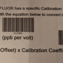
If you’ll be entering the data from the sensor’s calibration sheet instead, you’ll need to enter blanking voltage from the sheet (again, dividing by 2 because of the res-div). So let’s pretend the datasheet says the blanking offset is 0.02 volts, so divide that by 2 and get 0.01. And then the sheet gives you the calibration coefficient as ppb per volt (parts per billion per volt). So pretend a sensor’s datasheet said 1035.4234 ppb/v. So you could enter that number in the concentration line and 0.5v for the voltage (because that’s half of one volt), like this:
Arduino1234const float cyclopsPhycoStdConc = 1035.4234; // Concentration of the standard used// for a 1-point sensor calibration.const float cyclopsPhycoStdVolt = 0.5; // The voltage (in volts) measured for the conc_std.const float cyclopsPhycoBlankVolt = 0.01; // The voltage (in volts) measured for a blank. -
2024-11-08 at 6:26 PM #18732
Shannon,
Thank you for the confirmation and write up for the sketch setup. I just have the phycocyanin C-FLUOR. This is my first time soldering, so I’m practicing on another board before I commit on the MP screw terminal board.
Have you notice big differences between the calibration sheet versus your manual calibration? And for the manual calibration on the mayfly, is there a specific sketch you use to get the voltages?
-
2024-11-11 at 4:56 PM #18737
The calibration sheet from Turner was very accurate for the new sensor, so if you don’t want to buy expensive rhodamine standard right now, you’re probably fine to use the data from the sheet. But we’ve found that the sensors tend to drift over time so we do quarterly recalibrations of the sensors to make sure they’re still accurate.
Here’s a simple sketch to take 100 analog readings quickly and average them, then constantly repeat that, and printing all data to the serial port. Then I just copy/paste the text from the serial port into Excel so I can do an analysis and overall average.
Arduino123456789101112131415161718192021222324252627282930313233343536373839404142434445464748495051525354555657585960616263646566676869707172737475767778//Takes lots of readings from the EnviroDIY Mayfly's ADS1115 Aux Analog ADC and averages them, prints to screen#include <SPI.h>#include <Wire.h>#include <Adafruit_ADS1015.h>Adafruit_ADS1115 ads; // The Mayfly's ADS1115 Aux ADC is 16-bit versionfloat average_volts; //variable to hold the calculated averageint State8 = LOW;int State9 = LOW;int aux_channel = 0; //channel number of whatever pin you've got your input connected to for the ADS1115 Aux Analog chip (AA0 = 0, AA1 = 1, AA2 = 2, AA3 = 3)int readcount = 100; //the number of readings you want to take for each sampleint time_between_readings = 10; //number of milliseconds between each reading in a samplevoid setup(){Serial.begin(57600); //Start the serial connection with the computerads.begin(); //begin adafruit ADS1015pinMode(8, OUTPUT); // define the red and green LEDs as outputspinMode(9, OUTPUT);digitalWrite(8, HIGH); //turn on one of the LEDs to start withdigitalWrite(9, LOW);pinMode(22, OUTPUT); //switched power pin declared as outputdigitalWrite(22, HIGH); //turn on the Switched sensor voltageSerial.println("EnviroDIY Mayfly Aux-Analog Averaging Sketch ");Serial.print("Aux ADC Channel: ");Serial.print(aux_channel); Serial.print("(AA"); Serial.print(aux_channel);Serial.print(") Number of readings per sample: ");Serial.println(readcount);Serial.println("-------------------------------------------------------------");delay(2000); //wait 2 seconds}void loop(){auxanalog_sample(); //go take a measurement with the ADS1115//blink the red and green LEDs in alternating fashion on each loopif (State8 == LOW) {State8 = HIGH;} else {State8 = LOW;}digitalWrite(8, State8);State9 = !State8;digitalWrite(9, State9);// Serial.print("Averaged analog voltage (volts): "); //print the results to the serial monitorSerial.println(average_volts,5);delay(100); //wait a little bit between loops, adjust as you want} //end loopvoid auxanalog_sample() // function that takes reading from ADS1115 Aux Analog chip on Mayfly{int16_t adc_bits = 0; //int to hold the value of the bits that get readfloat bit_sum = 0.0; //sum of all the bits readfor (int i = 0; i < readcount; i++){adc_bits = ads.readADC_SingleEnded(aux_channel); //take a single-ended reading with the ADS1115bit_sum += adc_bits; //add the latest reading to the sumdelay(time_between_readings); //wait x milliseconds between readings, adjust as you want}float average_bits = bit_sum / readcount; //find the average by dividing the bit_sum by readcount//now convert bits into volts//average_volts = (average_bits * 3.3)/17585.0;// use this next line instead of the previous line if you're using a voltage divider to reduce an external sensor's voltageaverage_volts = ((average_bits * 3.3)/17585.0) * 2.0; //multiply by 2 if you used a 50/50 divider}
-
-
2024-12-13 at 5:43 PM #18794
Thank you for that info.
I need to tap another hole for the Turner device and was wondering if you have a size recommendation for a drill tap and waterproof cable gland.
-
2024-12-14 at 12:22 PM #18796
There’s information on this page, in Section 6.2 about the holes for the cable glands: https://www.envirodiy.org/knowledge-base/building-an-envirodiy-monitoring-station/
As mentioned on that page, the 1/2″ NPT cable glands require you to drill a 23/32” hole and tap it with a 1/2″ NPT tap. I don’t know what the diameter of the cable for your sensor is, but it’s probably between 0.2″ and 0.35″ so you can probably use McMaster-Carr part number 69915K54. The larger gland that comes with the EnviroDIY kit is for cables 0.24″ to 0.47″ (part number 69915K53) because of the rubber molded 3.5mm stereo plug on the end of the CTD cables. If your Turner cable is larger than 0.35″ you’ll need to use the larger size.
-
2025-03-06 at 5:58 PM #18966
Shannon, I went ahead and soldered four 10k resistors instead of the two I originally said, similar to what you did here:

Does that still work for my purposes or does it change things?
Thank you.
-
2025-03-06 at 8:43 PM #18967
Are you trying to measure 2 analog signals from 2 separate sensors with just one 6-pin screw terminal board?
-
2025-03-06 at 10:07 PM #18969
I’m just connecting one Turner phyco c-flour sensor.
I assume these resistor pairs are independent and shouldn’t affect how a single sensor reports.
Thank you for the previous response regarding the cable glands.-
2025-03-08 at 7:17 PM #18976
If you only have one C-FLUOR sensor, then you only need one pair of resistors, since there’s only one analog signal from the sensor. There ARE two ground wires, which is why I asked how many sensors you were using with this one screw terminal board. In order to connect two Turner analog sensors to a Mayfly Logger, it’s good to use 2 separate screw terminal boards, since each sensor needs 2 ground terminals.
-
-
2025-03-08 at 11:10 PM #18977
Since I am only using one C-FLOUR sensor, does having two pair of soldered resistors affect anything or should I redo the screw terminal board to only have one pair of resistors?
Thank you for the tip on needing two separate screw terminal boards because each C-FLOUR needing 2 ground terminals each.
-
2025-03-10 at 9:23 AM #18978
There’s nothing electrically wrong with having all 4 resistors populated on that board, but only one pair will be used for your sensor analog input, and the other pair will not be connected to anything and will therefore not be performing any function.
-
-
2025-03-21 at 4:59 PM #19000
We have been testing out the Turner C-FLUOR (PC) PHYCOCYANIN sensor and getting mixed results where we are not sure if it is the sensor, sketch, or something else.
When measuring pure di water we are getting readings of around 5 – 6 ppb in both an opaque jar and open jar with the sensor in a shade cap.
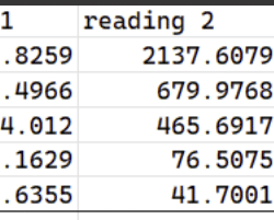
We bought blue spirulina (https://www.amazon.com/dp/B08233QMH4?ref=ppx_yo2ov_dt_b_fed_asin_title) and did 5 different ppb dilutions and here are the results that we got: attached below. It seems like the sensor is under reporting.
We will test again using blue spirulina that has a known phycocyanin concentration (https://www.amazon.com/dp/B08XC7KSRP?ref=ppx_yo2ov_dt_b_fed_asin_title).
Here is the C-FLUOR calibration cert: attached below.
Here is the partial sketch for the three sensors:
12345678910111213141516171819202122232425262728293031323334353637383940414243444546474849505152535455565758// ==========================================================================// Meter Hydros 21 Conductivity, Temperature, and Depth Sensor// ==========================================================================/** Start [hydros21] */#include <sensors/MeterHydros21.h>const char* hydrosSDI12address = "1"; // The SDI-12 Address of the Hydros 21const uint8_t hydrosNumberReadings = 6; // The number of readings to averageconst int8_t SDI12Power = sensorPowerPin; // Power pin (-1 if unconnected)const int8_t SDI12Data = 7; // The SDI12 data pin// Create a Meter Hydros 21 sensor objectMeterHydros21 hydros(*hydrosSDI12address, SDI12Power, SDI12Data,hydrosNumberReadings);/** End [hydros21] */// ==========================================================================// Campbell ClariVUE10 SDI-12 Turbidity Sensor// ==========================================================================/** Start [ClariVUE] */#include <sensors/CampbellClariVUE10.h>// NOTE: Use -1 for any pins that don't apply or aren't being used.const char* ClariVUESDI12address = "2"; // The SDI-12 Address of the ClariVUE10const int8_t ClariVUEPower = sensorPowerPin; // Power pinconst int8_t ClariVUEData = 7; // The SDI-12 data pin// NOTE: you should NOT take more than one readings. THe sensor already takes// and averages 8 by default.// Create a Campbell ClariVUE10 sensor objectCampbellClariVUE10 clarivue(*ClariVUESDI12address, ClariVUEPower, ClariVUEData);/** End [ClariVUE] */// ==========================================================================// Turner C-FLUOR Phycocyanin Sensor// ==========================================================================/** Start [cyclops] */#include <sensors/TurnerCyclops.h>// NOTE: Use -1 for any pins that don't apply or aren't being used.const int8_t cyclopsPhycoPower = sensorPowerPin; // Power pinconst uint8_t cyclopsPhycoNumberReadings = 10;const uint8_t cyclopsPhycoADSi2c_addr = 0x48; // The I2C address of the ADS1115 ADCconst int8_t cyclopsPhycoADSChannel = 0; // ADS channel// Cyclops calibration informationconst float cyclopsPhycoStdConc = 969.2924; // Concentration of the standard used// for a 1-point sensor calibration.const float cyclopsPhycoStdVolt = 0.5; // The voltage (in volts) measured for the conc_std.const float cyclopsPhycoBlankVolt = 0.0078; // The voltage (in volts) measured for a blank.// Create a Turner Cyclops sensor objectTurnerCyclops cyclopsPhyco(cyclopsPhycoPower, cyclopsPhycoADSChannel, cyclopsPhycoStdConc,cyclopsPhycoStdVolt, cyclopsPhycoBlankVolt, cyclopsPhycoADSi2c_addr,cyclopsPhycoNumberReadings);/** End [cyclops] */Another thing I notice is the Campbell ClariVUE10 skipping reporting intervals, while the other sensors seem fine. https://monitormywatershed.org/sites/TWI_testc/
It started happening after I switched my laptop to upload the sketch and used the ModularSensors_Dependencies_0.35.0 library. My previous laptop used an older 2022 library, but I had to copy and replace the CampbellClariVUE10.h file with a new version to get the turbidity sensor to work. Is the library version issue causing the reporting interval issues? Is having 2 sensors on the same SDI-12 data pin ok?
thank you.
-
2025-03-25 at 11:47 PM #19009
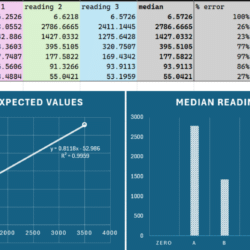
Here are the results with the blue spirulina that has a known phycocyanin concentration (https://www.amazon.com/dp/B08XC7KSRP?ref=ppx_yo2ov_dt_b_fed_asin_title). PPB readings are still off.
Campbell ClariVUE10 reporting intervals seems to be resolved when I went back to a library I downloaded back in Nov 2024 but kept the SRC-sensors folder from the ModularSensors_Dependencies_0.35.0, except I stuck with the Nov 2024 version of the CampbellClariVUE10.h file.
Attachments:
-
-
AuthorPosts
- You must be logged in to reply to this topic.

 Welcome to EnviroDIY, a community for do-it-yourself environmental science and monitoring. EnviroDIY is part of


