Home › Forums › Mayfly Data Logger › Low Cost EC sensor Station upgrade
Tagged: Low Cost, modify, ModularSensor
- This topic has 12 replies, 3 voices, and was last updated 2020-07-23 at 10:30 PM by
 Sara Damiano.
-
AuthorPosts
-
-
2020-04-08 at 12:05 PM #14038
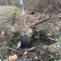
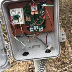
I currently have six of the subject sensor stations (Photo of GMI_EC2 attached) deployed and logging data to SD cards. I recently setup two of these stations using PlatformIO to load the DRWI_CitSci.ino code with the AtlasScientificEC.h patched in. This library function did not match my hardware which uses the Sensorex probe with the Atlas EZO circuit operating in UART communication mode. I attached a photo of my temporary setup to get the station uploading to MonMW with the EZO circuit set for I2C.
The mods I need to the Atlas Scientific ModularSensors library are shown in the following code snippets from my arduino IDE code which I am currently using.
12345//float K_temp = 0.034; //2/17/19 update with new LM35float m = -.0927, b = 72.653; //Calibration for RTD on Sensorex probefloat EC, EC25;float alpha; //Temperature correction to EC at 25Cfloat K0 = 0.018, K1 = 8E-5, K2 = 1E-6;12345//correct EC to 25C reference using data from Hanna 1413uS standardEC = sensorstring.toFloat();alpha = K2 * pow(Temp0, 2) + K1 * Temp0 + K0;EC25 = EC / (1 + alpha * (Temp0 - 25));addFloatToString(data, EC25, 4, 1);I am not a comp sci major so tweeking the ModularSensor library is way above my pay grade so any help would be appreciated.
Thanks
Attachments:
-
2020-04-10 at 10:51 AM #14060
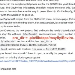
@srgdamiano I decided to go back to basics with ModularSensors – getting started but took a while to get PCsync to load. See attached screenshot with the corrections I had to make on the src_dir.
What is the function of the .pio folder and is it automatically populated when creating a new project? I had to manually load the .pio/mayfly folder from another project to get PCsync to load.
I finally got that all working and reporting the time on the serial monitor but when I launched PCsync.exe it responded with “no FTDI found” and I did have the code running in the mayfly and connected to my PC (Windows 10). Any thoughts where my problem may be?
Thanks
-
2020-04-10 at 10:54 AM #14062
I seem to have “detached” my screen shot
Attachments:
-
2020-04-16 at 10:35 AM #14081
Hi Sara @srgdamiano
I think I have gone as far as I am able on my Low Cost EC sensor project. I added #include <sensors/ExternalVoltage.h> to the DRWI_CitSci code and registered GMI_test site using new ExternalVoltage_Volt(&extvolt) from the Sensorex RTD votage divider as a proxy for temperature. I need to apply a simple linear correction (y=mx + b) to have the readings on MonMW in ºC rather than voltage.
Is there anyway to do this in the main code or do I need a new #include <AtlasSensorex.h> to do the job?
If so how hard would this be or more to the point could you add this to the ModularSensors library?
Thanks
-jim
-
2020-04-16 at 4:13 PM #14082
-
2020-04-16 at 4:37 PM #14083
-
2020-04-20 at 9:15 AM #14084
Hi Adam-
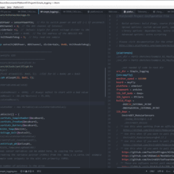
Thanks for getting back to me. Since my software expertise is limited and I don’t understand how all the code in ModularSensors works I have not been able to get “calculated variable” to compile in my simple_logging.ino code. I have been successful in getting the code to work with external_voltage and the Atlas EZO circuits (EC and pH). I attached a screenshot of what works with the calculated variable code commented out. I suspect my problem has something to do with pointers.
Your help would be appreciated. I probably need step by step instructions of if there simple fix to my code that would be great!
Thanks
-jim
Attachments:
-
2020-04-24 at 11:03 AM #14095
<h4 class=”user-nicename”>@chuckkir</h4>
Thanks Chuck for offering to help with my coding issues. I have two sets of code that I am currently testing with my Low Cost Sensor Station. Simple_logging.ino is working on my mayfly platform which I am using to test the compensation routines to convert the raw data from the AtlasScientific EC sensor and the RTD temperature probe to µS and ºC.123456789101112131415161718192021222324252627282930313233343536373839404142434445464748495051525354555657585960616263646566676869707172737475767778798081828384858687888990919293949596979899100101102103104105106107108109110111112113114115116117118119120121122123124125126127128129130131132133134135136137138139140141142143144145146147148149150151152153154155156157158159160161162163164165166167168169170171172173174175176177178179180181182183184185186187188189190191192193194195196197198199200201202203204205206207/*****************************************************************************simple_logging.inoWritten By: Sara Damiano (sdamiano@stroudcenter.org)Development Environment: PlatformIOHardware Platform: EnviroDIY Mayfly Arduino DataloggerSoftware License: BSD-3.Copyright (c) 2017, Stroud Water Research Center (SWRC)and the EnviroDIY Development TeamThis sketch is an example of logging data to an SD cardDISCLAIMER:THIS CODE IS PROVIDED "AS IS" - NO WARRANTY IS GIVEN.*****************************************************************************/// ==========================================================================// Defines for the Arduino IDE// In PlatformIO, set these build flags in your platformio.ini// ==========================================================================// ==========================================================================// Include the base required libraries// ==========================================================================#include <Arduino.h> // The base Arduino library#include <EnableInterrupt.h> // for external and pin change interrupts#include <LoggerBase.h> // The modular sensors library// ==========================================================================// Data Logger Settings// ==========================================================================// The name of this fileconst char *sketchName = "simple_logging.ino";// Logger ID, also becomes the prefix for the name of the data file on SD cardconst char *LoggerID = "TestRTD";// How frequently (in minutes) to log dataconst uint8_t loggingInterval = 1;// Your logger's timezone.const int8_t timeZone = -5; // Eastern Standard Time// NOTE: Daylight savings time will not be applied! Please use standard time!// ==========================================================================// Primary Arduino-Based Board and Processor// ==========================================================================#include <sensors/ProcessorStats.h>const long serialBaud = 115200; // Baud rate for the primary serial port for debuggingconst int8_t greenLED = 8; // MCU pin for the green LED (-1 if not applicable)const int8_t redLED = 9; // MCU pin for the red LED (-1 if not applicable)const int8_t buttonPin = 21; // MCU pin for a button to use to enter debugging mode (-1 if not applicable)const int8_t wakePin = 10; // MCU interrupt/alarm pin to wake from sleep// Set the wake pin to -1 if you do not want the main processor to sleep.// In a SAMD system where you are using the built-in rtc, set wakePin to 1const int8_t sdCardPwrPin = -1; // MCU SD card power pin (-1 if not applicable)const int8_t sdCardSSPin = 12; // MCU SD card chip select/slave select pin (must be given!)const int8_t sensorPowerPin = 22; // MCU pin controlling main sensor power (-1 if not applicable)// Create the main processor chip "sensor" - for general metadataconst char *mcuBoardVersion = "v0.5b";ProcessorStats mcuBoard(mcuBoardVersion);// ==========================================================================// Maxim DS3231 RTC (Real Time Clock)// ==========================================================================#include <sensors/MaximDS3231.h> // Includes wrapper functions for Maxim DS3231 RTC// Create a DS3231 sensor object, using this constructor function:MaximDS3231 ds3231(1);#include <sensors/ExternalVoltage.h>const int8_t ADSPower = sensorPowerPin; // Pin to switch power on and off (-1 if unconnected)const int8_t ADSChannel = 2; // The ADS channel of interestconst float dividerGain =1; // Default 1/gain for grove voltage divider is 10x// const uint8_t ADSi2c_addr = 0x48; // The I2C address of the ADS1115 ADCconst uint8_t VoltReadsToAvg = 1; // Only read one sampleExternalVoltage extvolt(ADSPower, ADSChannel, dividerGain, 0x48, VoltReadsToAvg);//==================================================// Atlas Scientific EZO//=============================================//#include <sensors/AtlasScientificEC.h>#include <sensors/AtlasScientificpH.h>//create EZO Object//AtlasScientificEC atlasEC(22, 0x64, 5); //I2C for EC = 0x64; pH = 0x63AtlasScientificpH atlaspH(22, 0x63, 5);/*float calculateVariableValue(void){float calculatedResult = -9999; // Always safest to start with a bad valuecalculatedResult = -30.141*extvolt + 75.359;return calculatedResult;}Variable *calculatedVar = new Variable(calculateVariableValue);*/Variable *variableList[] = {new ProcessorStats_SampleNumber(&mcuBoard),new ProcessorStats_FreeRam(&mcuBoard),new ProcessorStats_Battery(&mcuBoard),new MaximDS3231_Temp(&ds3231),new ExternalVoltage_Volt(&extvolt),//new Variable(calculateVariableValue)//new AtlasScientificEC_Cond(&atlasEC),new AtlasScientificpH_pH(&atlaspH),//new MaximDS3231_Temp(analogRead(A0))// Additional sensor variables can be added here, by copying the syntax// for creating the variable pointer (FORM1) from the <code>menu_a_la_carte.ino</code> example// The example code snippets in the wiki are primarily FORM2.};// Count up the number of pointers in the arrayint variableCount = sizeof(variableList) / sizeof(variableList[0]);// Create the VariableArray objectVariableArray varArray;// ==========================================================================// The Logger Object[s]// ==========================================================================// Create a logger instanceLogger dataLogger;// ==========================================================================// Working Functions// ==========================================================================// Flashes the LED's on the primary boardvoid greenredflash(uint8_t numFlash = 4, uint8_t rate = 75){for (uint8_t i = 0; i < numFlash; i++) {digitalWrite(greenLED, HIGH);digitalWrite(redLED, LOW);delay(rate);digitalWrite(greenLED, LOW);digitalWrite(redLED, HIGH);delay(rate);}digitalWrite(redLED, LOW);}// ==========================================================================// Main setup function// ==========================================================================void setup(){// Start the primary serial connectionSerial.begin(serialBaud);// Print a start-up note to the first serial portSerial.print(F("Now running "));Serial.print(sketchName);Serial.print(F(" on Logger "));Serial.println(LoggerID);Serial.println();Serial.print(F("Using ModularSensors Library version "));Serial.println(MODULAR_SENSORS_VERSION);// Set up pins for the LED'spinMode(greenLED, OUTPUT);digitalWrite(greenLED, LOW);pinMode(redLED, OUTPUT);digitalWrite(redLED, LOW);// Blink the LEDs to show the board is on and starting upgreenredflash();// Set the timezones for the logger/data and the RTC// Logging in the given time zoneLogger::setLoggerTimeZone(timeZone);// It is STRONGLY RECOMMENDED that you set the RTC to be in UTC (UTC+0)Logger::setRTCTimeZone(0);// Set information pinsdataLogger.setLoggerPins(wakePin, sdCardSSPin, sdCardPwrPin, buttonPin, greenLED);// Begin the variable array[s], logger[s], and publisher[s]varArray.begin(variableCount, variableList);dataLogger.begin(LoggerID, loggingInterval, &varArray);// Set up the sensorsSerial.println(F("Setting up sensors..."));varArray.setupSensors();// Create the log file, adding the default header to it// Do this last so we have the best chance of getting the time correct and// all sensor names correctdataLogger.createLogFile(true); // true = write a new header// Call the processor sleepdataLogger.systemSleep();}// ==========================================================================// Main loop function// ==========================================================================void loop(){dataLogger.logData();}Here is the code I currently have deployed on GMI_EC1 and GMI_test which is uploading the raw sensor data to MonMW.
123456789101112131415161718192021222324252627282930313233343536373839404142434445464748495051525354555657585960616263646566676869707172737475767778798081828384858687888990919293949596979899100101102103104105106107108109110111112113114115116117118119120121122123124125126127128129130131132133134135136137138139140141142143144145146147148149150151152153154155156157158159160161162163164165166167168169170171172173174175176177178179180181182183184185186187188189190191192193194195196197198199200201202203204205206207208209210211212213214215216217218219220221222223224225226227228229230231232233234235236237238239240241242243244245246247248249250251252253254255256257258259260261262263264265266267268269270271272273274275276277278279280281282283284285286287288289290291292293294295296297298299300301302303304305306307308309310311312313/*****************************************************************************DWRI_CitSci.inoWritten By: Sara Damiano (sdamiano@stroudcenter.org)Development Environment: PlatformIOHardware Platform: EnviroDIY Mayfly Arduino DataloggerSoftware License: BSD-3.Copyright (c) 2017, Stroud Water Research Center (SWRC)and the EnviroDIY Development TeamThis sketch is an example of logging data to an SD card and sending the data toboth the EnviroDIY data portal as should be used by groups involved withThe William Penn Foundation's Delaware River Watershed InitiativeDISCLAIMER:THIS CODE IS PROVIDED "AS IS" - NO WARRANTY IS GIVEN.*****************************************************************************/// ==========================================================================// Defines for the Arduino IDE// In PlatformIO, set these build flags in your platformio.ini// ==========================================================================#ifndef TINY_GSM_RX_BUFFER#define TINY_GSM_RX_BUFFER 64#endif#ifndef TINY_GSM_YIELD_MS#define TINY_GSM_YIELD_MS 2#endif// ==========================================================================// Include the base required libraries// ==========================================================================#include <Arduino.h> // The base Arduino library#include <EnableInterrupt.h> // for external and pin change interrupts#include <LoggerBase.h> // The modular sensors library// ==========================================================================// Data Logger Settings// ==========================================================================// The name of this fileconst char *sketchName = "DWRI_CitSci.ino";// Logger ID, also becomes the prefix for the name of the data file on SD cardconst char *LoggerID = "GMI_EC2";// How frequently (in minutes) to log dataconst uint8_t loggingInterval = 5;// Your logger's timezone.const int8_t timeZone = -5; // Eastern Standard Time// NOTE: Daylight savings time will not be applied! Please use standard time!// ==========================================================================// Primary Arduino-Based Board and Processor// ==========================================================================#include <sensors/ProcessorStats.h>const long serialBaud = 115200; // Baud rate for the primary serial port for debuggingconst int8_t greenLED = 8; // MCU pin for the green LED (-1 if not applicable)const int8_t redLED = 9; // MCU pin for the red LED (-1 if not applicable)const int8_t buttonPin = 21; // MCU pin for a button to use to enter debugging mode (-1 if not applicable)const int8_t wakePin = 10; // MCU interrupt/alarm pin to wake from sleep// Set the wake pin to -1 if you do not want the main processor to sleep.// In a SAMD system where you are using the built-in rtc, set wakePin to 1const int8_t sdCardPwrPin = -1; // MCU SD card power pin (-1 if not applicable)const int8_t sdCardSSPin = 12; // MCU SD card chip select/slave select pin (must be given!)const int8_t sensorPowerPin = 22; // MCU pin controlling main sensor power (-1 if not applicable)// Create the main processor chip "sensor" - for general metadataconst char *mcuBoardVersion = "v0.5b";ProcessorStats mcuBoard(mcuBoardVersion);// ==========================================================================// Wifi/Cellular Modem Settings// ==========================================================================// Create a reference to the serial port for the modemHardwareSerial &modemSerial = Serial1; // Use hardware serial if possible// Modem Pins - Describe the physical pin connection of your modem to your boardconst int8_t modemVccPin = 23; // MCU pin controlling modem power (-1 if not applicable)const int8_t modemStatusPin = 19; // MCU pin used to read modem status (-1 if not applicable)const int8_t modemLEDPin = redLED; // MCU pin connected an LED to show modem status (-1 if unconnected)// Network connection informationconst char *apn = "hologram"; // The APN for the gprs connection// For the Sodaq 2GBee R6 and R7 based on the SIMCom SIM800// NOTE: The Sodaq GPRSBee doesn't expose the SIM800's reset pin#include <modems/Sodaq2GBeeR6.h>const long modemBaud = 9600; // SIM800 does auto-bauding by defaultSodaq2GBeeR6 modem2GB(&modemSerial,modemVccPin, modemStatusPin,apn);// Create an extra reference to the modem by a generic name (not necessary)Sodaq2GBeeR6 modem = modem2GB;// ==========================================================================// Maxim DS3231 RTC (Real Time Clock)// ==========================================================================#include <sensors/MaximDS3231.h>// Create a DS3231 sensor objectMaximDS3231 ds3231(1);//==================================================// Atlas Scientific EZO//=============================================#include <sensors/AtlasScientificEC.h>//create EZO ObjectAtlasScientificEC atlasEC(22, 0x64, 5);// ==========================================================================// Creating the Variable Array[s] and Filling with Variable Objects// ==========================================================================#include <sensors/ExternalVoltage.h>const int8_t ADSPower = sensorPowerPin; // Pin to switch power on and off (-1 if unconnected)const int8_t ADSChannel = 2; // The ADS channel of interestconst float dividerGain =1; // Default 1/gain for grove voltage divider is 10x// const uint8_t ADSi2c_addr = 0x48; // The I2C address of the ADS1115 ADCconst uint8_t VoltReadsToAvg = 1; // Only read one sample//float testVar = 2.123;// Create an External Voltage sensor objectExternalVoltage extvolt(ADSPower, ADSChannel, dividerGain, 0x48, VoltReadsToAvg);Variable *variableList[] = {new MaximDS3231_Temp(&ds3231),new ProcessorStats_Battery(&mcuBoard),new Modem_RSSI(&modem),new ExternalVoltage_Volt(&extvolt), //Proxy for Senorex RTD Temperaturenew AtlasScientificEC_Cond(&atlasEC), //raw uncompensated EC// new Modem_SignalPercent(&modem),};// *** CAUTION --- CAUTION --- CAUTION --- CAUTION --- CAUTION ***// Check the order of your variables in the variable list!!!// Be VERY certain that they match the order of your UUID's!// Rearrange the variables in the variable list if necessary to match!// *** CAUTION --- CAUTION --- CAUTION --- CAUTION --- CAUTION ***const char *UUIDs[] = // UUID array for device sensors{"242afd8d-fa49-4b8e-9a97-17f9c2dd0677", // Temperature (EnviroDIY_Mayfly_Temp)"1aeb9498-66a3-4b68-b41c-0160aa94e627", // Battery voltage (EnviroDIY_Mayfly_Batt)"534a9a46-c122-48ac-892f-e7bd340fdef3", // Received signal strength indication (Sodaq_2GBee_RSSI)"f5d30b8e-fce5-42c8-aad4-530845b5646b", // Temperature (SensorexTemp)"cf26c1bd-2dad-411a-8d2b-4e4b94808084" // Specific conductance (SensorexCond)};const char *registrationToken = "8cb70410-d480-4a05-a4dd-a810fe816ce6"; // Device registration tokenconst char *samplingFeature = "8f5a37a7-4729-43b5-bdbb-043d6a5ed90e"; // Sampling feature UUID// Count up the number of pointers in the arrayint variableCount = sizeof(variableList) / sizeof(variableList[0]);// Create the VariableArray objectVariableArray varArray(variableCount, variableList, UUIDs);// ==========================================================================// The Logger Object[s]// ==========================================================================// Create a new logger instanceLogger dataLogger(LoggerID, loggingInterval, &varArray);// ==========================================================================// A Publisher to WikiWatershed// ==========================================================================// Device registration and sampling feature information can be obtained after// registration at http://data.WikiWatershed.org// Create a data publisher for the EnviroDIY/WikiWatershed POST endpoint#include <publishers/EnviroDIYPublisher.h>EnviroDIYPublisher EnviroDIYPOST(dataLogger, &modem.gsmClient, registrationToken, samplingFeature);// ==========================================================================// Working Functions// ==========================================================================// Flashes the LED's on the primary boardvoid greenredflash(uint8_t numFlash = 4, uint8_t rate = 75){for (uint8_t i = 0; i < numFlash; i++) {digitalWrite(greenLED, HIGH);digitalWrite(redLED, LOW);delay(rate);digitalWrite(greenLED, LOW);digitalWrite(redLED, HIGH);delay(rate);}digitalWrite(redLED, LOW);}// Read's the battery voltage// NOTE: This will actually return the battery level from the previous update!float getBatteryVoltage(){if (mcuBoard.sensorValues[0] == -9999) mcuBoard.update();return mcuBoard.sensorValues[0];}// ==========================================================================// Main setup function// ==========================================================================void setup(){// Start the primary serial connectionSerial.begin(serialBaud);// Print a start-up note to the first serial portSerial.print(F("Now running "));Serial.print(sketchName);Serial.print(F(" on Logger "));Serial.println(LoggerID);Serial.println();Serial.print(F("Using ModularSensors Library version "));Serial.println(MODULAR_SENSORS_VERSION);Serial.print(F("TinyGSM Library version "));Serial.println(TINYGSM_VERSION);Serial.println();// Start the serial connection with the modemmodemSerial.begin(modemBaud);// Set up pins for the LED'spinMode(greenLED, OUTPUT);digitalWrite(greenLED, LOW);pinMode(redLED, OUTPUT);digitalWrite(redLED, LOW);// Blink the LEDs to show the board is on and starting upgreenredflash();// Set the timezones for the logger/data and the RTC// Logging in the given time zoneLogger::setLoggerTimeZone(timeZone);// It is STRONGLY RECOMMENDED that you set the RTC to be in UTC (UTC+0)Logger::setRTCTimeZone(0);// Attach the modem and information pins to the loggerdataLogger.attachModem(modem);modem.setModemLED(modemLEDPin);dataLogger.setLoggerPins(wakePin, sdCardSSPin, sdCardPwrPin, buttonPin, greenLED);// Begin the loggerdataLogger.begin();// Note: Please change these battery voltages to match your battery// Set up the sensors, except at lowest battery levelif (getBatteryVoltage() > 3.4){Serial.println(F("Setting up sensors..."));varArray.setupSensors();}// Sync the clock if it isn't valid or we have battery to spareif (getBatteryVoltage() > 3.55 || !dataLogger.isRTCSane()){// Synchronize the RTC with NIST// This will also set up the modemdataLogger.syncRTC();}// Create the log file, adding the default header to it// Do this last so we have the best chance of getting the time correct and// all sensor names correct// Writing to the SD card can be power intensive, so if we're skipping// the sensor setup we'll skip this too.if (getBatteryVoltage() > 3.4){Serial.println(F("Setting up file on SD card"));dataLogger.turnOnSDcard(true); // true = wait for card to settle after power updataLogger.createLogFile(true); // true = write a new headerdataLogger.turnOffSDcard(true); // true = wait for internal housekeeping after write}// Call the processor sleepSerial.println(F("Putting processor to sleep\n"));dataLogger.systemSleep();}// ==========================================================================// Main loop function// ==========================================================================// Use this short loop for simple data logging and sendingvoid loop(){// Note: Please change these battery voltages to match your battery// At very low battery, just go back to sleepif (getBatteryVoltage() < 3.4){dataLogger.systemSleep();}// At moderate voltage, log data but don't send it over the modemelse if (getBatteryVoltage() < 3.55){dataLogger.logData();}// If the battery is good, send the data to the worldelse{dataLogger.logDataAndPublish();}} -
2020-05-12 at 12:06 PM #14156
Thanks Chuck for getting my Sensorex RTD voltage divider output converted to °C. I plan to leave the EC as the raw value from the AtlasScientific EZO circuit. Attached is the code addition to DRWI_CitSci.ino to get the Sensorex probe data published to MonMW:
123456789101112131415161718192021222324252627282930313233343536373839404142434445464748//==================================================// Atlas Scientific EZO//=============================================#include <sensors/AtlasScientificEC.h>//create EZO ObjectAtlasScientificEC atlasEC(22, 0x64, 5);// ==========================================================================// calculate temperature from RTD voltage divider// ==========================================================================#include <sensors/ExternalVoltage.h>const int8_t ADSPower = sensorPowerPin; // Pin to switch power on and off (-1 if unconnected)const int8_t ADSChannel = 2; // The ADS channel of interestconst float dividerGain =1; // Default 1/gain for grove voltage divider is 10x// const uint8_t ADSi2c_addr = 0x48; // The I2C address of the ADS1115 ADCconst uint8_t VoltReadsToAvg = 1; // Only read one sample//float testVar = 2.123;// Create an External Voltage sensor objectExternalVoltage extvolt(ADSPower, ADSChannel, dividerGain, 0x48, VoltReadsToAvg);ExternalVoltage_Volt sensorVoltage(&extvolt);// Linear correction coeficients of RTD with 10K ohm voltage dividerconst float TemperatureMultipiler = -30.141; //m, Sensorex RTDconst float TemperatureConstant = 75.359; //b, Sensorex RTD// Create a function to calculate centigrade from the voltagefloat calcTemp(void){float voltage = sensorVoltage.getValue(true);return voltage = TemperatureMultipiler * voltage + TemperatureConstant;}// ==========================================================================// Creating the Variable Array[s] and Filling with Variable Objects// ==========================================================================Variable *variableList[] = {new MaximDS3231_Temp(&ds3231),new ProcessorStats_Battery(&mcuBoard),new Modem_RSSI(&modem),new Variable(calcTemp, 1,"temperature", "Degree Celsius","waterTemp",""),new AtlasScientificEC_Cond(&atlasEC),// new Modem_SignalPercent(&modem),}; -
2020-07-23 at 9:00 PM #14379
Hi Sara @srgdamiano
I haven’t used PIO for several months but in preparation for the transition from 2G to 4G I launched PIO this week and it apparently did an upgrade and now my code won’t load.
I get the following error:
avrdude: stk500_getsync() attempt 10 of 10: not in sync: resp=0x00
PIO is currently core 4.3.4 and home 3.2.3
Any help on this would be appreciated.
Thanks
-
2020-07-23 at 9:12 PM #14380
Is your Mayfly turned on and plugged in? That error means your Mayfly isn’t being detected.
-
2020-07-23 at 10:15 PM #14381
Thanks. I am using the FTDI port and wiggled some plugs, etc and now is loading ok. I assume when I was getting that error the mayfly was plugged in and turned on because when I attempt to load with the pwr switch turned off I get the following error:
Uploading .pio\build\mayfly\firmware.hexavrdude: ser_open(): can’t open device “\\.\COM4”: Access is denied.avrdude done. Thank you.*** [upload] Error 1I guess a bad connection somewhere. -
2020-07-23 at 10:30 PM #14382
The access is denied error doesn’t mean the Mayfly is off, it means something else (another program or window on your computer) is monopolizing that serial port. Usually you see it when you try to upload a program or start a serial port monitor when another serial port monitor was already running.
If you have the Mayfly plugged directly into the USB of your computer and the Mayfly is off, the error is more to the effect that the serial port doesn’t exist, not access is denied. If you’re using something like an ftdi friend between the Mayfly and your computer, you’ll see avrdude sync errors if the Mayfly is off.
-
-
AuthorPosts
- You must be logged in to reply to this topic.

 Welcome to EnviroDIY, a community for do-it-yourself environmental science and monitoring. EnviroDIY is part of


