Home › Forums › Mayfly Data Logger › Mayfly 1.1 powering review & analysis
- This topic has 3 replies, 1 voice, and was last updated 2022-05-19 at 1:10 PM by
 neilh20.
-
AuthorPosts
-
-
2022-04-06 at 5:44 PM #16902
The new Mayfly 1.1 has some great new features, though they may not ALL be visible until you look at the schematic.
A lot of hard work, has gone into the new Mayfly 1.0 and now Mayfly 1.1, and I would like to thank Shannon for creating and sharing it, and for being open to discussing some parts of the powering system. A small computer board takes a lot of skill to get right and produce it so it can be sold in volume, and there is often some risk in new circuits. The details are at envirodiy.org/mayfly/hardware/ and envirodiy.org/hardware-status-and-availability/
I would also like to thanks everyone at SWRC for their technical leadership in using rugged environmental sensors/transducers to automate measurements in the real physical world and publish them on the cloud https://monitormywatershed.org/browse/ . Really fantastic to have EnviroDIY.org to discuss it.
I’ve been working with the Mayfly 1.1 powering ~ so sharing a review and analysis, from the new LiIon battery charger, and +12V and what might be needed to estimate battery capacity ~ and some extension to ModularSensors I’m doing … https://github.com/neilh10/ModularSensors/wiki/docs/Envirodiy Mayfly1x.pdf
-
2022-04-08 at 3:48 PM #16906
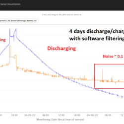
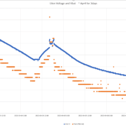
Here are some graphs of measured Vbat(10bit) with a software filtering that I’ve just completed. Its using a 2minute reading sample time – the electronic noise is hopefully similar when used on 15minute sampling intervals.
For the Mayfly 1.1 & Adafruit PkCell 4400mAh, I’ve run it for 4days interfacing over Modbus/RS485 in a critical voltage range of 3.85V dropping 0.2V to 3.65V.
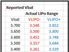
Vbat is under reading the LiIon Voltage by 0.1V, and still having some noise break through during this period of 0.1V, but much better than unfiltered.
The two graphs are of the same period, one is from MMW that is a little easier to understand and annotated however has different scales for the Vbat/LiIonV. The second is from an xls graph, using the same scale, and has the quantization more visible.My conclusion is when using Vbat for determing energy available – use a filtered version of Vbat, and be conservative with the estimated low battery voltage.
I can submit my Vbat software filtering if it would be useful.
neilh10/ModularSensors/blob/release1/src/sensors/ProcessorStats.cpp #175 only for AVR.I use the Vbat threshold for determing when to cease reliable wireless transmission, and only store readings locally, ready for when battery energy is restored, and then bulk upload of readings.
neilh10/ModularSensors/blob/release1/src/BatteryManagement.h #192Of course your specific LiIon battery may be different, the Pkcell 4400 is designed for cycle life > 500 charge/discharges (not specified for a daily partial discharge/recharge). Once working, the depth of the battery discharge could indicate when the battery needs replacing.
-
2022-05-18 at 2:23 PM #17021
An update on measuring battery voltage. I’ve purchased a number of Mayfly1.1 for a project. And on testing one of this batch, the noise level of measuring LiPo is better – which is great. The noise level of resistors is part of their specification, or it might be just luck in this case. Often a batch of noisy resistors is because the manufacture has selected out the low noise resistors.
The testing is at my office desk – which as I am finding out, is also electrically a noisy environment.
For release testing I’ve moved it to an outside environment and the noise level is even better, which is soooo nice.
Here is the graph of the lower noise measurement, where there is a cutoff of transmitting data at LiPo=3.8V (measured from A6 Blue line) with a more accurate 12bit measurement (black line).
This is 4 days of testing, with accelerated 2min readings and if the LiPo V was above 3.8V immediately transmitted to MMW. When it dropped below 3.8V it queued the readings. Then when the solar came back, charged the battery and the readings went up 3.8V, it transmitted the data. The black line is the more accurate 12bit reading, which in this specific Mayfly the blue line A6 is fairly accurate.
Graph with Mayfly A6 and more accurate 12bit
Attachments:
-
2022-05-19 at 1:10 PM #17025
For powering I am using the new Solar2 connector.
It requires a very precise diameter solid core wire – and took me some time to find it as old fashioned “Bell Wire” 20AWG, which I got from local Lowes store.
The needs to be – 20-26 AWG solid core. It also needs exactly matched wire strippers. If the wire strippers are too small a dia, its likely to nick the solid core wire, making it more prone to failure.
The connector is
“Phoenix 1778832″,”TERM BLOCK PLUG 2POS STR 2.5MM” and requires
or digikey https://www.digikey.com/en/products/detail/phoenix-contact/1778832/2625556
Another nifty new feature I found with Mayfly1.x is soldering the SJ17 LED10 Blue “- which at least for Digi modules is “network connection”. It activates when the module comes out of sleep, then when the device is connecting to the network it flashes. And finally when it disconnects from the network it turns off. A good help in checking operations, and slight waste of power for normal operation. Normally I like to have a LED activate when there is maintenance activity – (say for 10minutes after reset, or on a maintenance wake button press operation) but that has to be designed in at system level, either sw or hw and not figured that out yet.
-
-
AuthorPosts
- You must be logged in to reply to this topic.

 Welcome to EnviroDIY, a community for do-it-yourself environmental science and monitoring. EnviroDIY is part of


