Home › Forums › Mayfly Data Logger › Ver 0.3 Mayfly Grove Power Supply
Tagged: Grove, mayfly data logger
- This topic has 4 replies, 2 voices, and was last updated 2016-06-30 at 4:18 PM by
John Smutny.
-
AuthorPosts
-
-
2016-06-29 at 11:05 AM #1621
Problem: Haven’t been able to send 5V power to the Digital and Analog Grove Headers. The Headers are constantly supplied with 3.3V
I have a question about the Notice on the Mayfly “Jumper Settings” page regarding the board’s internal boost regulator (here is the note)…
“Note: due to a manufacturing issue on Mayfly version 0.3, some boards have an incorrect boost regulator and cannot produce 5 volts, so they only output 3.3v on the “5v_switched” pin.”
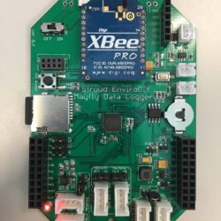
I am concerned that my board my be one that is effect by this issue but I want to be certain. To test whether the Grove headers could supply 5V I have set Pin D22 to HIGH in my software (signified by the Red LED in the lower left hand corner) and tested the voltage distributed by the 5V/3.3V pin headers for Grove Headers “AA0-AA1”, “AA2-AA3”, “D6-7”, & “D10-11” using a voltmeter. After measuring the voltage with both jumper orientations (5V then 3.3V), the Grove Headers were constantly provided with 3.3V.
Question: Is there any other way to enable 5V to the Grove headers through Software and/or Hardware?
Attachments:
-
2016-06-29 at 5:41 PM #1625
If you measure 3.3v on the Sw_5v pin, then unfortunately you have a board with the incorrect regulator. There’s no way to get your board to generate 5v unless you replace the regulator. While it is possible to replace it if you have the right tools and you have experience removing and replacing a SOT-23 surface mount device. However, we have new boards with the correct part that we have shipped to Amazon to replace the existing inventory. I will also be contacting each customer directly through Amazon to tell them how they can exchange any affected boards for a new one.
Keep in mind that most users will not need to use the 5v setting on the Grove connector jumper. The Mayfly is not tolerant of 5v I/O signals, so any peripheral devices you connect must not send any voltage greater than 3.3v back to the Mayfly I/O pins. The 5v options is only there for experienced users who can ensure that they have proper level-shifting circuitry or other protective measures to ensure that the Mayfly only sees 3.3v signals. In my case, I use several analog sensors that need to be powered by 5v supply, but only output a 0-2.5v signal. Other digital sensors that require 5v will be connected to a level-shifting adapter board via the Grove connector.
-
2016-06-30 at 8:45 AM #1629
Ok, I have checked the datasheets to my sensors and none of them output a voltage greater than 3.3V (2 are digital sensors while another supplies a max of 2.4V), so thanks for the heads up.
Unfortunately, I do not have any experience replacing regulators on a SOT-23 surface mount, therefore I am curious on how soon this replacement process can occur or if you need me to do anything to start the process.
-
2016-06-30 at 3:34 PM #1632
See my latest blog post for information about exchanging the v0.3 Mayfly boards for the new v0.4 boards. I will also be emailing all of the Amazon customers today with information about the exchange.
-
2016-06-30 at 4:18 PM #1633
Done, thank you for the help
-
-
-
-
AuthorPosts
- You must be logged in to reply to this topic.

 Welcome to EnviroDIY, a community for do-it-yourself environmental science and monitoring. EnviroDIY is part of