
Home › Forums › Mayfly Data Logger › Why is 12V power on Mayfly V1.1 (rev A) nominally only 11.3V?
- This topic has 4 replies, 2 voices, and was last updated 2025-02-10 at 3:42 PM by
jpeytonj.
-
AuthorPosts
-
-
2025-02-07 at 10:57 AM #18882
Hello there,
I have a question about the 12V power on Mayfly V1.1. Among the changes listed in the rev A design (https://www.envirodiy.org/mayfly/hardware/details-and-specs/) it states that the “12v boost circuit… can now source up to 100mA, although the nominal output voltage is ~11.3v”.
I am curious why the nominal output is 11.3V rather than 12V. I looked at the datasheet for the MCP1665T-E/MRA (see link below) and your design seems identical to the datasheet’s first ‘Typical Application’ (with 20K and 180K feedback resistors) which is supposed to give a 12V output.
https://ww1.microchip.com/downloads/en/DeviceDoc/20005872A.pdf
Is the datasheet wrong or is there some other reason why the output voltage is only 11.3V?
Many thanks!
-
2025-02-07 at 2:37 PM #18883
In 2021, there was one small production run of the Mayfly v1.1 RevA boards that, due to an error by the manufacturer, used an incorrect resistor value for the 12-volt boost circuit, resulting in a lower output voltage, around 11.3v. This was corrected in the next manufacturing run, along with making a few other changes, which is why the v1.1 RevB version came out in early 2022. There were notes on the product websites (here and Amazon) at the time the RevA boards were for sale, stating that the 12v output was lower than ideal. We also designed and built the 12-volt Boost Screw Terminal Grove Adapter at that time so that people could use that to generate a proper 12-volt supply for sensors that might be sensitive to the 11.3v directly from the board. It’s also useful for people who still have a Mayfly 0.5v or earlier version, allowing them to generate 12v (or 9v) because those older boards only had onboard 3v and 5v output. Any of the v1.1 RevB boards that have been available since mid-2022 generate the proper voltage with the onboard 12v boost circuitry.
-
2025-02-07 at 4:32 PM #18884
Thank you so much!
So just to be clear, there was no design change in the 12V boost from v1.1 Rev A to v1.1 Rev B, just a correction in the resistor used during manufacture? Were any other aspects of the design changed at this time?
If so, maybe it would be helpful to add some Rev B documentation to the “Changes” list shown on this page: https://www.envirodiy.org/mayfly/hardware/details-and-specs/ (or if not, maybe it would be helpful to note that the Rev A and Rev B designs are identical even if their manufacture was different)
-
2025-02-10 at 3:33 PM #18888
Mayfly v1.0RevA had a Max17250 boost chip that used the following resistors in order to set the output voltage at 12 volts:
R15 = 10k
R19 = 84.5k
R31 = 220kWhen it was time to manufacture more boards in 2021, there was a semiconductor shortage that made it impossible to find that particular boost converter, so the design was modified to use a MCP1665 instead. However, the first small run of Mayfly v1.1RevA boards used the resistors above from the previous circuit instead of the correct values below:
R15 = 20k
R19 = 180k
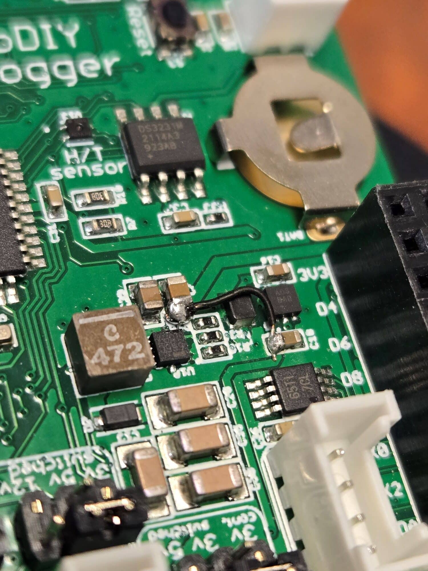
R31 = 470kThe input power selection options for the MCP1665 also didn’t behave like the Max17350 did, so before we shipped out any Mayfly boards from that run, I put a blob of silicone conformal coating on the back of the boards to cover SJ26 to make it unusable and also made a note about it on the schematic. I also manually soldered a tiny black wire onto each board to connect the power circuit properly, as denoted by the blue line in the schematic and shown in the attached photo below.
So when it came time for the next production run, we opted to call it v1.1RevB since it would correct the problem with the incorrect resistors, add a trace to connect power circuits properly (to take the place of the black wire), and remove solder jumper SJ26 from the back of the board since it was no longer needed. We also switched the ICSP connector from a small 2×3 0.5mm pitch header to a Tac-connect connector.
Someone asked this question about version differences a few years ago on the Technical Questions thread, and you can see my specific response here.
So in summary, the schematic currently on the website for v1.1RevA was what we designed, however the 3 resistor values placed by the manufacturer are different than specified in the documentation. This affected only a small number of boards because we quickly made a new production run for v1.1RevB. However not all of the documentation in various locations got updated with the latest specs. I’ll go back and add a note to the v1.1RevA schematic to clarify which resistors were actually used on that batch, and will also update the Details and Specs page to more clearly state the specs of the current v1.1RevB board.
Attachments:
-
-
2025-02-10 at 3:42 PM #18890
Wow! Thank you again.
I am so impressed by your detailed, expert, and helpful response.
-
-
AuthorPosts
- You must be logged in to reply to this topic.